3-22
SM-18006
TROUBLESHOOTING
● CheckingMethodUsingCheckingMode
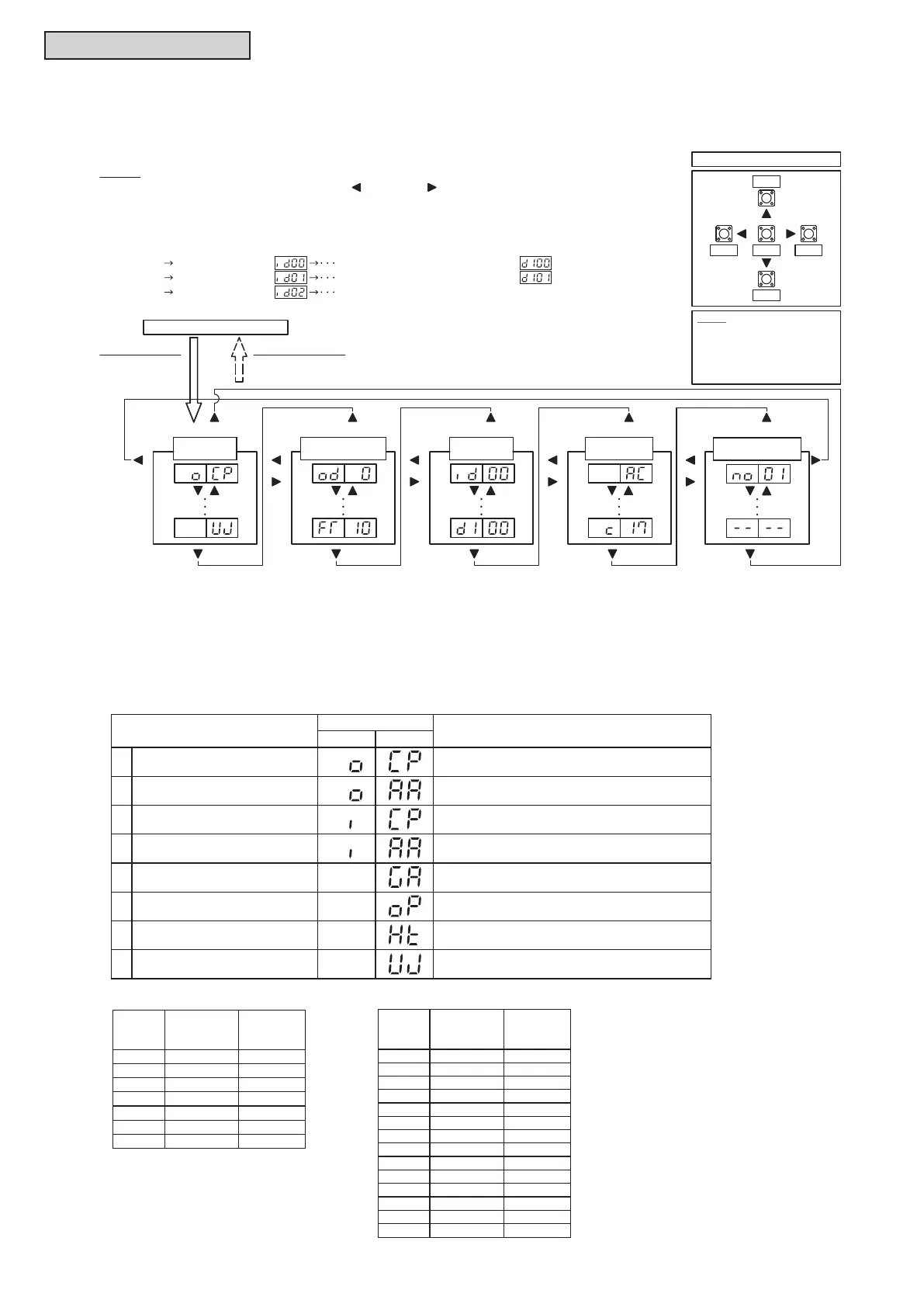
Operating conditions and each part of a system can be checked using the 7-segment display on PCB1 in
the water source unit.
PSW2PSW4
PSW5
PSW3
PSW2
PSW2
PSW4
PSW4
PSW5
PSW3
PSW2
PSW4
PSW5
PSW3
PSW2
PSW4
PSW5
PSW3
PSW2
Normal Mode (No indication)
Arrangement of Push Switches
NOTES:
1. Change the Indication Group by pressing PSW5 ( ) and PSW3 ( ).
The first indication of the next or the previous Indication Group will be indicated no matter where the current step is at.
2. The indications compatible for all the water source units and indoor units connected will be indicated
for the case of Group (B) and Group (C).
Notice
Make sure to cancel Checking
Mode after checking is
completed.
If not, system may operate
abnormally.
To Start Checking
Press PSW1 for
more than 3sec
To Cancel Checking
Press PSW1 for
more than 3sec
PSW4
PSW5
PSW2
PSW4
PSW2PSW4 PSW2PSW4PSW2PSW4
Indication Group (A)
Connecting
Information
PSW3
Indication Group (D)
Alarm Code
Information
Indication Group (C)
Indoor Unit
Information
Indication Group (E)
Alarm Code History
Information
Indication Group (B)
Water Source Unit
Information
PSW4
PSW2
PSW3PSW1PSW5
(0-1) Indoor Unit (no.0)(Group B) (0-8) Cause Code of Indoor Unit Stoppage
(Example: Group C)
(1-1) Indoor Unit (no.1) (1-8) Cause Code of Indoor Unit Stoppage
(2-1) Indoor Unit (no.2) (Group D)
(A) Connecting Information
This information is displayed at main water source unit (Unit A) only.
Press PSW4 (▼) to move forward or PSW2 (▲) to move backward.
The information is displayed alternately as “Item” → “Details”.
Item
7-Segment Display
Details
SEG2 SEG1
1
Total Capacity of
Connected Water Source Units
Total Capacity of W.S. Combination
2 Connected W.S. Number Connected Water Source Unit Number
3
Total Capacity of
Connected Indoor Units
Total Capacity of Connected Indoor Units
4 Connected I.U. Number Connected Indoor Unit Number
5 Refrigerant Cycle No. Refrigerant Cycle No.
6 Total Capacity of Operated I.U.
Total Capacity of Operated Indoor Units
Refer to “Indoor Unit Capacity Table”.
Refer to “Water Source Unit Capacity Table”.
7 Total Comp. Frequency [Hz]
8 Accumulated Operation Time [10 Hour]
Indoor Unit Capacity Table
Indication
Refrigeration
Ton
[RT]
6 006 0.5
8 008 0.7
12 012 1.0
15 015 1.3
18 018 1.5
24 024 2.0
27 027 2.3
30 030 2.5
36 036 3.0
48 048 4.0
54 054 4.5
60 060 5.0
72 072 6.0
96 096 8.0
Type
(Capacity)
[MBH]
Indication
Refrigeration
Ton
[RT]
Type
(Capacity)
[MBH]
Water Source Unit Capacity Table
72 072 6.0
96 096 8.0
120 120 10.0
144 144 12.0
168 168 14.0
192 192 16.0
216 216 18.0



 To Next Page