SM-18006
3-41
TROUBLESHOOTING
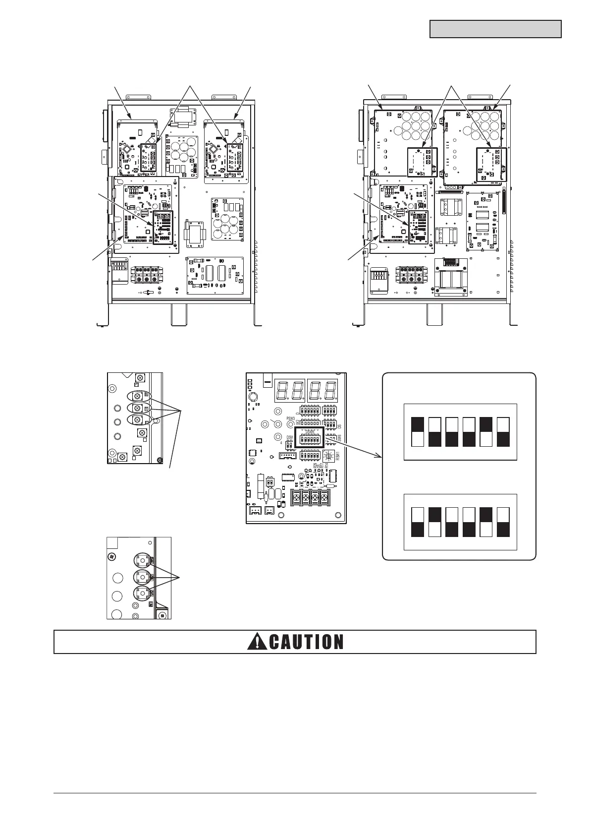
Inverter Compressor 1 Failure
Inverter Compressor 2 Failure
C95
C92
C11
CN100
1
ON
32
DSW8
C121
CN101
RSW1
C26
D1
R102
TB2
IC10
L3
R3
D50
D51
Z2
Z1
C78
C77
IC3
D5
R17
LED3
C79
IC2
C82 C81
CN46
LED4
DSW10
R151
EF1
CN16
103 222
102
101
103
333
333
152
+
0
9
8
7
6
5
4
3
2
1
DSW6
DSW1
DSW5
DSW2
DSW3 DSW7
DSW4
3
ON
5 641 2
3
ON
5 641 2 1
ON
3 42
1
ON
3 423
ON
5 641 2
3
ON
5 641 2 1
ON
3 42
1
ON
2
+
PSW4
PSW5
PSW1
PSW3
PSW2
C9
102
R14
102
R29
Q8
Q10
222
R141
C118
4702
4303
R222
8202
R220
C119
C130
C131
1 2 3 4 5 6
ON
DSW5
1 2 3 4 5 6
ON
DSW5
Terminals of
Inverter Compresso
Wiring (3 pcs.)
● 208/230V Type
Terminals of Inverter
Compressor Wiring (3 pcs.)
(A) Part
Inverter PCB (INV1 or INV2)
(B) Part
Water Source Unit PCB (PCB1)
(C) Part
Inverter PCB (INV1 or INV2)
P
W
V
U
T
S
1P
N
● 460V Type
• Measuretheinsulationresistanceofafailedcompressor.
Donotperformanemergencyoperationwhentheinsulationresistanceis0Ω.
The other compressors may be damaged because there is a possibility that refrigerant oil is
oxidized.
• In this emergency operation, compressor frequency cannot be controlled normally.
Therefore, an alarm code “07”, “43”, “44”, “45” or “47” may display on the LCD.
• Thisemergencyoperationmaynotprovidesufcientcoolingandheatingcapacity.
• This operation is a temporary emergency operation when the inverter compressor is damaged.
Therefore, replace it with the new one as soon as possible.
• Turn OFF DSW5-No.1 and No.2 of the water source unit PCB after replacing the compressor.
If this setting is not performed, the inverter compressor will be damaged.
(B)
(B)



 To Next Page