SM-18006
3-45
TROUBLESHOOTING
l
TheRUNindicator(red)ashes.
l
The indoor unit number (refrigerant cycle number - address number), the alarm code, the model code
1
,
the model name
1
and the number of connected indoor units are displayed on the LCD. The water source
unit number and the alarm code are displayed on the 7-segment display of the water source unit PCB.
Note 1: Except for some models.
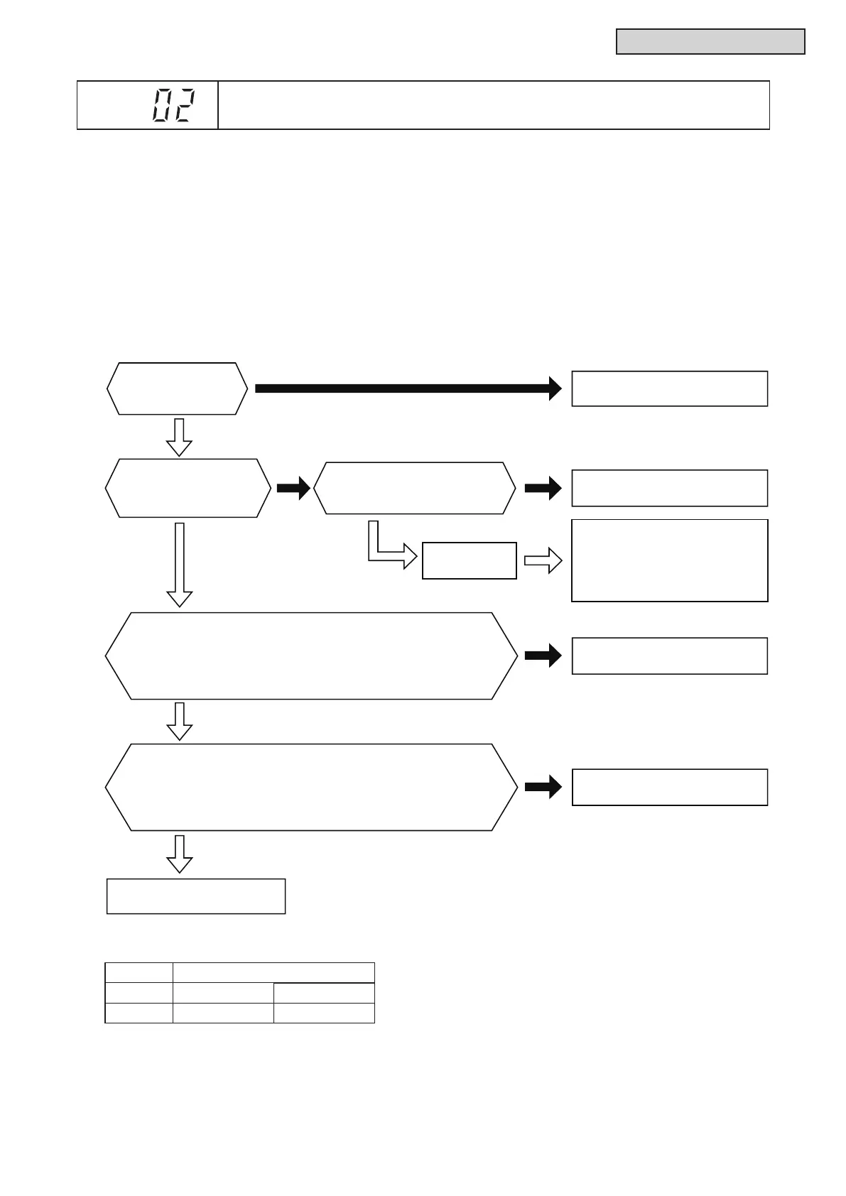
This alarm code is displayed when the high pressure switch (PSH) is activated during the compressor
operation (RY is turned ON).
W.S. PCB: Water Source Unit PCB (PCB1)
No
No
Yes
Yes
No
No
Yes
Are connectors in
the table 1 connected
correctly?
Is voltage applied between #4 and #6 of CN5 on main power
PCB (MPB) approx. DC13V when power is ON but stop operation?
Is voltage applied between #4 and #6 of CN5 approx. 0V
when transmit the operation to inverter compressor (approx. 5 sec.
passed after turning ON the controller)?
Faulty Inverter PCB (INV).
Replace it.
Attach the connectors correctly.
Normal inverter
PCB
Faulty W.S. PCB (PCB1).
Replace it.
Connect the terminals correctly.
Check activation of the following
safety devices.
Remove the cause after checking.
● High Pressure Switch (PSH):
602 psi (4.15MPa)
Do connectors in
the table 1 have continuity
when the water source
unit stops operating.
Is the terminal correctly
connected to the high pressure
switch on the discharge pipe?
No
Is voltage applied between #4 and #5 of CN6 on main power
PCB (MPB) approx. DC13V when power is ON but stop operation?
Is voltage applied between #4 and #5 of CN6 approx. 0V
when transmit the operation to inverter compressor (approx. 5 sec.
passed after turning ON the controller)?
Faulty main power PCB (MPB).
Replace it.
Yes
Yes
■208/230VType
T
able 1. Connector Number
PCB Main Power PCB (MPB)
Connector CN5 CN6
Pin No. #4, #6 #4, #5
Alarm
Code
Activation of Protection Device in Water Source Unit