SM-18006
3-47
TROUBLESHOOTING
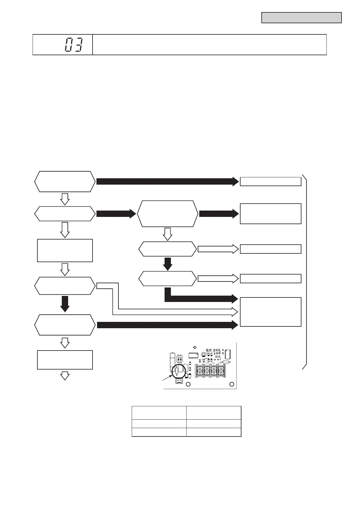
Is LED3 (yellow)
on W.S. PCB ON?
No
No
Yes
Yes
Yes
Is DSW10-1P (pin)
(Terminating Resistance)
on W.S. PCB ON?
Is LED1 (red)
on W.S. PCB ON?
Set it correctly.
Disconnect wiring of
TB2-No.1 and No.2
on W.S. PCB.
1
Yes
Reconnect wiring of
TB2-No.1 and No.2
on W.S. PCB.
Replace noise filter.
No
Check wiring
of connector PCN1.
Faulty W.S. PCB
Water
Unit
No
No
No
Is the fuse for
noise filter blown?
Yes
Replace fuse.
Is the fuse for
W.S. PCB blown?
Yes
Yes
Is the voltage
between connector
PCN1-No.1 and No.2
of W.S. PCB correct?
2
Is resistance of
R151 on W.S. PCB
75Ω±5%?
l
TheRUNindicator(red)ashes.
l
The indoor unit number (refrigerant cycle number - address number), the alarm code, the model code
1
,
the model name
1
and the number of connected indoor units are displayed on the LCD. The alarm code
is displayed on the 7-segment display of the water source unit PCB.
Note 1: Except for some models.
This alarm code is displayed when an abnormal condition continues for three minutes after normal
communication between indoor units and water source units. The abnormal condition continues for 30
seconds even after the micro-computer is automatically reset. If communication failure occurs from the
beginning, the alarm code is displayed after 30 seconds from start up.
When fuses are blown, or the circuit breakers are activated, check the cause of overcurrent and take
necessary action.
Power Supply
Connector PCN1
Voltage
208/230V60Hz 208/230V
460V60Hz 230V
Note2:CorrectVoltage
W.S. PCB: Water Source Unit PCB (PCB1)
C92
CN101
TB2
R3
Z2
Z1
C78
C77
IC3
D5
R17
LED3
C79
IC2
C82C81
DSW10
R151
EF1
103 222
102
101
103
333
333
+
1
ON
2
C9
102
R14
102
R29
Q8
Q10
Water Source Unit PCB
(PCB1)
Alarm
Code
Abnormal Communication between Indoor Units and Water Source Units



 To Next Page