SM-18006
3-51
TROUBLESHOOTING
l
TheRUNindicator(red)ashes.
l
The indoor unit number (refrigerant cycle number - address number), the alarm code, the model code
1
,
the model name
1
and the number of connected indoor units are displayed on the LCD. The alarm
code, the water source unit number of abnormal inverter PCB and abnormal inverter PCB number are
displayed on the 7-segment display of the water source unit PCB.
Note 1: Except for some models.
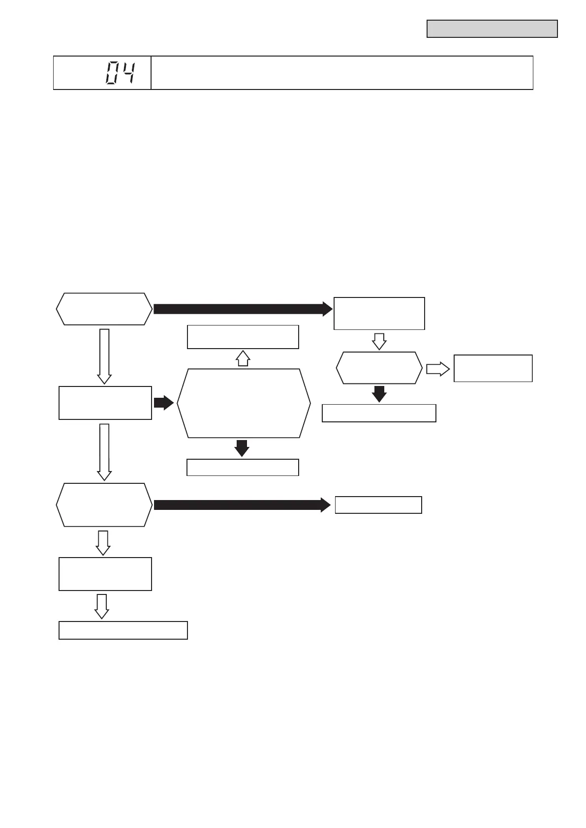
This alarm code is displayed when an abnormal condition continues for 30 seconds after normal
communication between the water source unit PCB and the inverter PCB. The abnormal condition continues
for 30 seconds even after the micro-computer is automatically reset. If communication failure occurs from
the beginning, the alarm code is displayed after 30 seconds from start up.
Yes
Disconnect
CN14 and CN20
of W.S. PCB
Is LED2 (green) on
W.S. PCB flashing?
LED203 on the
inverter PCB (INV)
is turned ON.
The setting of
DSW101 on
the inverter PCB (INV)
is correct (sec 3.1.3).
Yes
The connections between
inverter PCB (INV) and
reactor (DCL),
main power PCB (MPB)
are correct.
Also, other connections for
inverter PCB (INV) are correct.
Check limiting resistance
of incoming current.
Check the wiring
between W.S. PCB and
inverter PCB (INV).
Correctly connect wires
No
Yes
Is LED2 (green) on
W.S. PCB flashing?
Check the W.S. PCB (P3-53)
Yes
No
Check the inverter
PCB
1
(INV).
No
Yes
No
Correctly set wires.
Yes
Check the inverter PCB
1
(P3-53).
Yes
W.S. PCB: Water Source Unit PCB (PCB1)
■208/230VType
Alarm
Code
Abnormal Communication between Inverter PCB and Water Source Unit PCB



 To Next Page