JOHNSON CONTROLS
106
FORM 145.05-NOM7
ISSUE DATE: 10/31/2019
SECTION 5 – SEQUENCE OF OPERATION
• OPTIONS key, SUPPLY SYSTEM subsection:
“DUCT HIGH STATIC SWITCH” must be set to
ENABLED
Sequence of Operation
If the duct high static switch input is lost for 5 seconds,
the Unit Controller initiates a “WRN – HIGH DUCT
PRESSURE 1" fault and shut down the unit.
If the duct high static switch input is not reestab-
lished after 60 seconds, the Unit Controller initiates a
“LOCKOUT HIGH DUCT PRESS” fault.
If the duct high static switch is reestablished within 60
seconds, the unit removes the “WRN – HIGH DUCT
PRESSURE 1" fault, resume normal operation, and set
the HIGH STATIC COUNTER to 1.
If the duct high static switch input is not lost during
the next 60 minutes, the HIGH STATIC COUNTER is
reset to 0.
If the duct high static switch input is lost for 5 seconds
a second time within 60 minutes, the Unit Controller
initiates a “WRN – HIGH DUCT PRESSURE 2” fault,
shut down the unit, and set the HIGH STATIC COUN-
TER to 2.
If the duct high static switch input is lost for 5 seconds
a third time within 60 minutes, the Unit Controller ini-
tiates a “LOCKOUT HIGH DUCT PRESS” fault and
shut down the unit.
A “LOCKOUT HIGH DUCT PRESS” fault is only re-
set by cycling power to the control by using the shut-
down input.
Supply Fan Airow Measurement
Order the LSWU unit with an airflow measuring de-
vice installed at the factory and labeled on the unit's
option tag. Enable and set up the piezometer using the
Unit Interface.
How It Works: The System is based on the principle
of a flow nozzle. The inlet cone of the fan is used as
the flow nozzle, and the flow is calculated by mea-
suring the static pressure drop through the inlet cone.
The pressure drop is measured from the tap located on
the face of the inlet cone to the piezometer ring in the
throat. The inlet tap is connected to the high-pressure
side of the transducer and the piezometer ring is con-
nected to the low-pressure side. The transducer sends
a DC signal to the control board on CTB1-20, and the
program calculates a CFM rating for air flow.
If “SUPPLY FAN PIEZOMETER” is set to NOT IN-
STALLED (OPTIONS key, SUPPLY FAN subsection),
SUPPLY AIRFLOW is not calculated or displayed. If it
is set to INSTALLED, the following is used to calcu-
late SUPPLY AIRFLOW.
• SETPOINT key, SUPPLY FAN subsection: the
“PIEZOMETER K-FACTOR” is set using the
range 0.00 to 10,000 (default is 8869)
The calculations are derived for the supply air density
by using SUPPLY AIR TEMP CURRENT and UNIT
INSTALLED ALTITUDE. Interpolate using Table 26
on page 142.
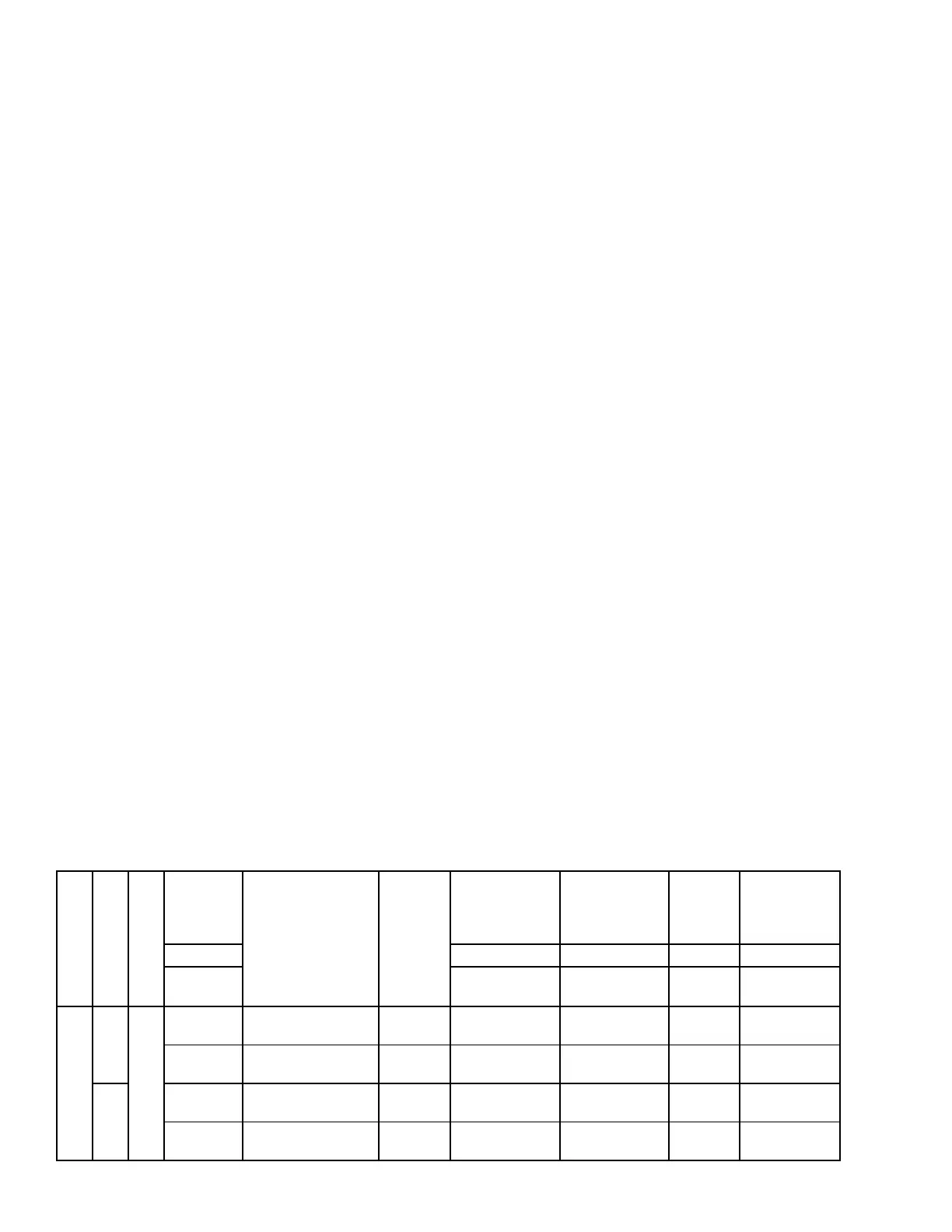
TABLE 20 - PIEZOMETER AIRFLOW MEASUREMENTS
CABINET SIZE
MODEL
FAN TYPE
FAN
DIAMETER
FAN MODEL
FAN
VENDOR
FAN
ONLY
FAN W/
PIEZORING
K
FACTOR
EXAMPLE
CALCULATED
AIRFLOW @
4.0 IN.WG.
INCHES P/N P/N k CFM
CFM =
KX√(IN.WG)
Small
LSWU025
Airfoil Plenum Fan
(SWSI)
25 NAPAF 25 COMEFRI 026 42640 100 026 42640 TBD 4608.2 9216
28 NAPAF 28 026 42641 100 026 42641 TBD 6277.8 12556
LSWU032
25 NAPAF 25 COMEFRI 026 42640 100 026 42640 TBD 4608.2 9216
28 NAPAF 28 026 42641 100 026 42641 TBD 6277.8 12556