JOHNSON CONTROLS
143
SECTION 6 – USER INTERFACE CONTROL CENTER
FORM 145.05-NOM7
ISSUE DATE: 10/31/2019
6
SECTION 6 – USER INTERFACE CONTROL CENTER
USER INTERFACE CONTROL CENTER
The User Interface is used to commission, monitor, and
troubleshoot the unit. It provides access to operational
data, parameter programming, and access to past “his-
tory” information that was recorded at the time of a
unit or system fault.
The User Interface is installed in the low voltage con-
trol compartment of the unit.
The User Interface uses a flexible membrane style key-
pad and has an 80 character (2 lines of 40 characters)
liquid crystal display. The display has a lighted back-
ground for night viewing and can be viewed in direct
sunlight. The backlighting energizes when any button
is pressed.
The keypad allows complete control of the system
from a central location. The keypad offers a multitude
of commands available to access displays, program pa-
rameters, and initiate system commands. The keypad
consists of thirty-six keys, that are divided into three
categories, Data Entry, Navigation, and Menu Selec-
tion keys. A description of each of the keys is contained
below.
Data Entry Keys
The Data Entry Keys provide a means to enter values
for items that support edits. The keys available to sup-
port numeric input are the 0 through 9 keys, the deci-
mal key, the +/- key, the X key and the key. The keys
available to support choice input are the ◄ key, the
► key, the X key, and the key. Editing is started by
pressing the key. Once editing has started, the user
must press either the key or the X key. Any other
key press results in the “Press or X to Exit” mes-
sage displayed for two seconds. If you try to edit an
item that is view only, it is ignored by the menu system.
Some changes to the unit's operation may
require the shut down of the unit at the
control switch on front before it accepts
the change.
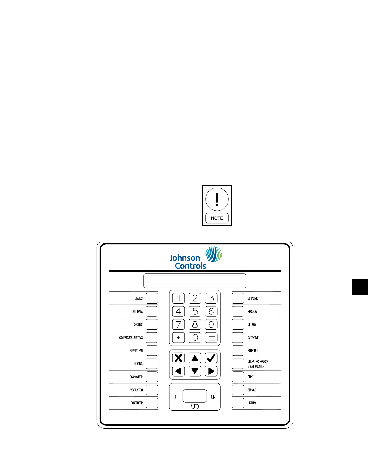
LD16445
FIGURE 79 - USER INTERFACE CONTROL PANEL