JOHNSON CONTROLS
152
FORM 145.05-NOM7
ISSUE DATE: 10/31/2019
SECTION 6 – USER INTERFACE CONTROL CENTER
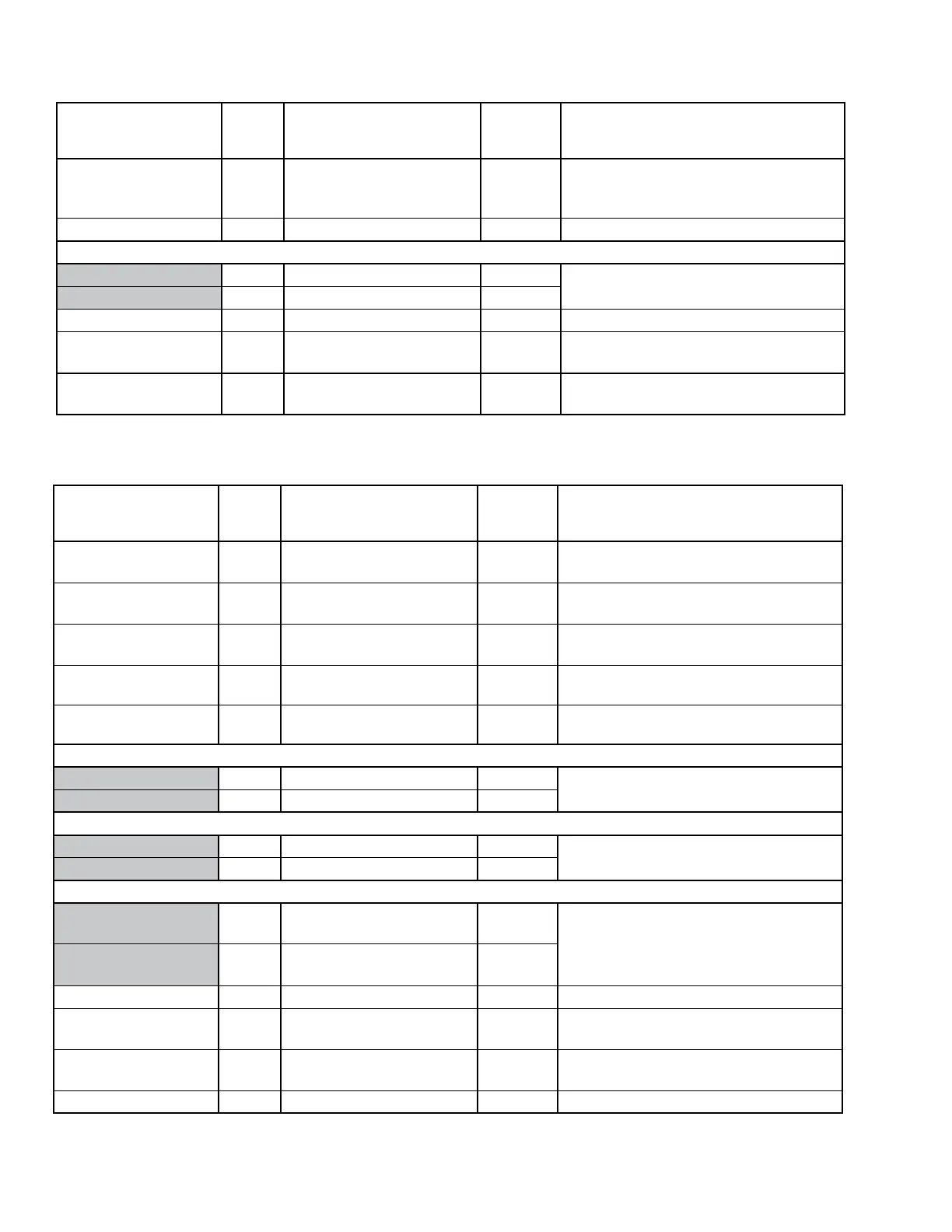
TABLE 34 - VENTILATION
DISPLAY TEXT
PASS
WORD
LEVEL
RANGE DEFAULT SHOW WHEN UNIT TYPE IS
Vent System Status
Normal - Active/ Normal
- Inactive / Faulted / User
Disabled / None
Derived Always
Damper Hardware 2 None / 2 Position/ Standard None Always
OA Damper Position
Current 0.0 to 100% Derived
Damper Hardware does not equal NONE
Active SP 0.0 to 100% Derived
Comfort Ventilation 1 Enabled / Disabled Disabled UNIT TYPE equals CONSTANT VOLUME
Ventilation Control 1 Fixed Minimum
Fixed
Minimum
Damper Hardware does not equal NONE
Isolation Damper
Control
User Disabled → User En-
abled
User
Disabled
Always
TABLE 35 - CONDENSER
DISPLAY TEXT
PASS
WORD
LEVEL
RANGE DEFAULT SHOW WHEN UNIT TYPE IS
Condenser Type 2 Water Cooled
Water
Cooled
Always
Condenser Water
Control
2 User Enabled / User Disabled
User
Enabled
Cond Valve Installed is not NONE
Cond Valve Installed 2
None / Cond Only / Cond W/
Bypass
Cond Only Condenser Type is WATER COOLED
Cond Water Valve Pos Cond Valve Min Pos To 100% Derived
Cond Valve Installed is COND ONLY or
COND W/ BYPASS
Bypass Valve Position
0 % To Cond Bypass Max
Pos
Derived
Cond Valve Installed equals COND W/
BYPASS
Discharge Press
Minimum 0.0 to 650.0 PSIG Derived
Cond Valve Installed is not NONE
SP Min 1 0.0 to 650.0 PSIG 225 PSIG
Discharge Press
Maximum 0.0 to 650.0 Psig Derived
Cond Valve Installed is not NONE
SP Max 1 0.0 to 650.0 Psig 400 PSIG
Water Temperature
Entering -20.0°F to 180.0°F
Look Up
Table
Condenser Type is WATER COOLED
Leaving -20.0°F to 180.0°F
Look Up
Table
Cond Water Flow Yes / No Derived Water Flow Switch equals INSTALLED
Condenser Pressure
P1 Output
0 to 100% Derived
Cond Valve Installed is COND ONLY or
COND W/ BYPASS
Flush Cycle 1
User Enabled
User Disabled
User Dis-
abled
Economizer Installed is WATERSIDE
Flush Delay Time 1 0 to 60 Min. 0 Economizer Installed is WATERSIDE