JOHNSON CONTROLS
17
SECTION 2 – INSTALLATION
FORM 145.05-NOM7
ISSUE DATE: 10/31/2019
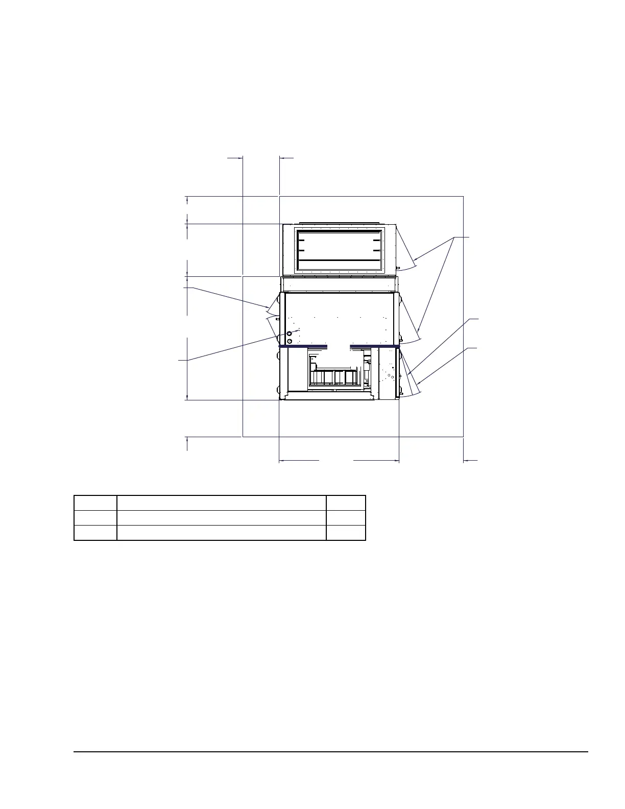
FIGURE 7 - RECOMMENDED SERVICE AND MAINTENANCE CLEARANCE WITH AIRSIDE ECONOMIZER
(LSW_025–040)
24 inch clearance required
on standard units, 3 inch
clearance required on units
with low clearance option.
24 inch clearance required on
standard units, 3 inch clearance
required on units with low clear-
ance option.
Removable door
with hinges. One
door handle and
tool operated latch.
Entry door standard 32
inch wide x 44 inch high
nominal with one door
handle and tool operated
latch.
Electrical panel door. Non
removable with hinges.
One door handle and tool
operated latch.
Optional when clearance
is available. Removable
doors with hinges. One
door handle and one tool-
operated latch.
Removable internal
panel is provided for
access to water valves
when no leftside clear-
ance is required.
78.37
inch
42 inch
Clearance
18 inch Clearance
FRONT
COIL SECTION
FILTER SECTION
REAR
AIRSIDE
ECONOMIZER
LEFT
RIGHT
FAN
SECTION
34.22
inch
“A”
075-83768-909 REV A
NO. FILTER OPTIONS “A”
1 4 inch lter 76.43
2 4 inch prelter + 4 inch high efciency lter 80.68
NOTE:
1. All dimensions are in inches.