JOHNSON CONTROLS
196
FORM 145.05-NOM7
ISSUE DATE: 10/31/2019
SECTION 8 – SERVICE
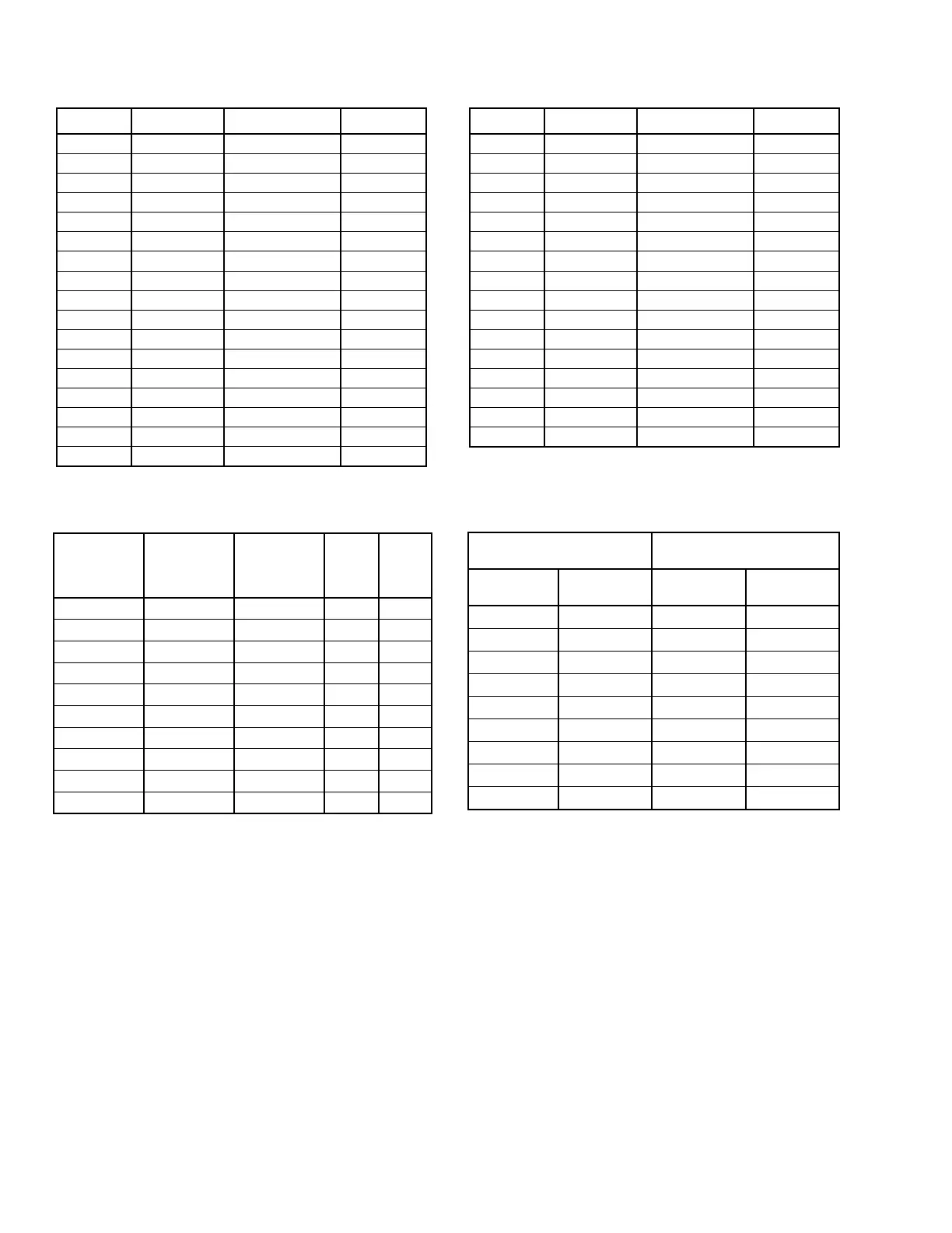
TABLE 45 - DUCT PRESSURE TRANSDUCER
1.25 "W.C.
SPAN
DIFFERENTIAL
INPUT PRESS
2.5 "W.C. SPAN
DIFFERENTIAL
INPUT PRESS
5.0 "W.C. SPAN
DIFFERENTIAL
INPUT PRESS
VOLT-
AGE 1-5
VDC
VOLT-
AGE
0-5VDC
0.0 0.0 0.0 1.0 0.50
0.156 0.312 0.625 1.5 1.00
0.312 0.625 1.25 2 1.50
0.468 0.937 1.875 2.5 2.00
0.625 1.25 2.5 3 2.50
0.781 1.562 3.125 3.5 3.00
0.938 1.875 3.75 4 3.50
1.094 2.187 4.375 4.5 4.00
1.25 2.5 5 5 4.50
5.00
Discharge Pressure Transducer
The discharge Pressure Transducer is located in the
discharge line for each refrigerant system. The purpose
of this transducer is to sense and convert the discharge
pressure into a DC voltage. The DC voltage is sent
to the Unit Controller where it is used to control the
condenser water volume when the unit is in cooling
operation. The discharge pressure value, in PSIG, is
displayed by the User Interface.
On units with R-410A refrigerant, the Discharge Trans-
ducer has a range of 0 to 600 PSIG, with a linear output
of 0 to 4.5VDC. Table 46 illustrates the DC volt output
from the transducer for a given discharge pressure.
Suction Pressure Transducer
The optional suction pressure transducer is located in
the common suction line of the compressors for each
refrigerant circuit. The purpose of the transducer is to
sense and convert the suction pressure to a DC voltage.
The DC voltage is sent to the Unit Controller where it
is displayed by the User Interface. When this option
is installed the Unit Controller also calculates and dis-
plays the Evaporator Superheat value for the system.
On units with R-410A refrigerant, the Suction Trans-
ducer has a range of 0 to 400 PSIG, with a linear output
of 0 to 4.5VDC. Table 46 illustrates the DC volt output
from the transducer for a given suction pressure.
TABLE 46 - PRESSURE TRANSDUCERS
0-400 PSIG SUCTION PRES-
SURE TRANSDUCER
0-600 PSIG DISCHARGE
PRESSURE TRANSDUCER
PRESSURE
PSIG
VOLTAGE
VDC
PRESSURE
PSIG
VOLTAGE
VDC
0 0.5 0 0.5
50 1.0 75 1.0
100 1.5 150 1.5
150 2.0 225 2.0
200 2.5 300 2.5
250 3.0 375 3.0
300 3.5 450 3.5
350 4.0 525 4.0
400 4.5 600 4.5
°F VOLTAGE RESISTANCE °C
-25 0.49 139,639 -30.6
-20 0.53 127,453 -28.9
-15 0.60 109,624 -26.1
-10 0.69 94,519 -23.34
-5 0.78 81,665 -20.55
0.0 0.88 70,750 -17.78
5 0.98 61,418 -15.00
10 1.10 53,426 -12.22
15 1.22 46,582 -9.44
20 1.35 40,703 -6.67
25 1.48 35,639 -3.89
30 1.62 31,269 -1.11
35 1.77 27,490 1.67
40 1.91 24,219 4.44
45 2.06 21,377 7.22
50 2.21 18,900 10.00
55 2.36 16,744 12.78
TABLE 44 - TEMPERATURE SENSOR RESISTANCE
°F VOLTAGE RESISTANCE °C
60 2.51 14,681 15.56
65 2.66 13,216 18.33
70 2.80 11,771 21.11
75 2.94 10,502 23.89
80 3.08 9,388 26.67
85 3.21 8,404 29.45
90 3.33 7,537 32.22
95 3.45 6,770 35.0
100 3.56 6,090 37.78
105 3.66 5,487 40.56
110 3.76 4,951 43.34
115 3.85 4,475 46.11
120 3.94 4,050 48.89
125 4.02 3,671 51.66
130 4.09 3,332 54.44
135 4.16 3,029 57.22