JOHNSON CONTROLS
161
SECTION 6 – USER INTERFACE CONTROL CENTER
FORM 145.05-NOM7
ISSUE DATE: 10/31/2019
6
SERVICE
To enter Service Mode, press the SERVICE key. The
following message is the initial screen and is displayed
when the SERVICE key is pressed, unless a Level 2
password is active.
Service
Enter password
All the DIGITAL outputs (DO) except for the compres-
sors can be forced ON. The LOCAL STOP switch must
be in the OFF position to force the outputs. To force an
output ON use the ◄ or ► key to navigate to the SER-
VICE DO section. Use the ▲ or ▼ key to select the
output you want to force ON. Press the
key and use
the ► key to switch it from OFF to ON. Press the
key again to energize the output. Repeat the above pro-
cess in reverse to turn the forced output back to OFF.
All the ANALOG outputs (AO) can be forced ON. To
force the outputs the LOCAL STOP switch must be in
the OFF position. Use the ◄ or ► key to navigate to
the SERVICE AO section To force an output ON. Use
the ▲ or ▼ key to select the output you want to force
ON. Press the
key and use the numeric key pad to
enter the output value. Press the
key again to ener-
gize the output. Repeat the above process in reverse
to turn the forced output back to 0.0. Failure to do so
leaves the forced output value in place until a different
value is initiated by the operation of the unit.
The ► key can be used to jump to the beginning of the
next section of displays and the ◄ key can be used to
jump to the beginning of the previous section of dis-
plays. The sections of displays are as follows:
• Parameters
• Data Log Format
• Data Log Error
• Update Flash
• Update Flash Error
• Factory Run Test
• Digital Outputs
• Analog Outputs
• Analog Inputs
• Digital Inputs
• Communication
• BAS Input Status.
• Unit Controller Internal Data - not for field
use.
• Device Object Instance.
• Communication Port Setup.
• Unit Controller Error data - not for field use.
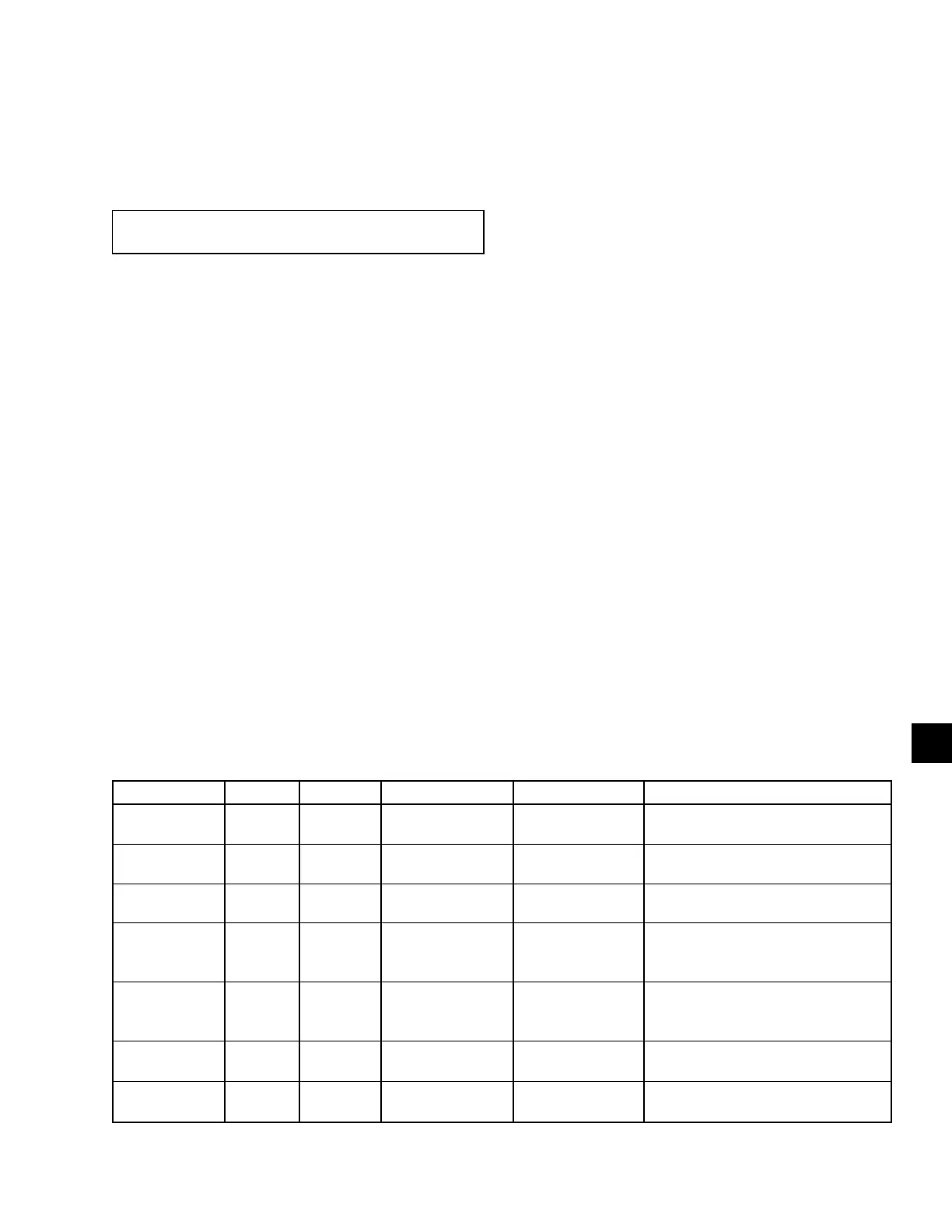
Table 40 on page 161 lists the Displayed Text, Input
or Output type, Unit Controller terminal location (ID),
Value Range, and when item is displayed.
TABLE 40 -
SERVICE
DISPLAY TEXT TYPE ID VALUE RANGE LOCATION DESCRIPTION
Duct Static
Press 1
Analog
Input
J10-2 0-5 Volts I/O Board
Analog Input from the Supply Air
Pressure Transducer #1
Duct Static
Press 2
Analog
Input
J10-5 0-5 Volts I/O Board
Analog Input from the Supply Air
Pressure Transducer #2
Evap Press
Temp Current
Analog
Input
J10-05 0-5VDC
Flex Evap
Temp Current
Analog
Input
J9-10 0-5 Volts I/O Board
Analog Input from the Temperature
Sensors Positioned on the Leaving
Side of the Evaporator Coil
Mixed Air
Temp
Analog
Input
J9-8 0-5 Volts I/O Board
Analog Input from the Temperature
Sensor Positioned before the Evapo-
rator Coil
Mx Supply Air
Temp Current
Analog
Input
J9-2 0-5 Volts I/O Board
Analog Input from the Supply or
Mixed Air Sensor
Outside Air
Humidity
Analog
Input
J11-2 0-5 Volts I/O Board
Analog Input from the Outdoor Air
Humidity Sensor