Installation—Installing the FC-2000 65
izm8conn
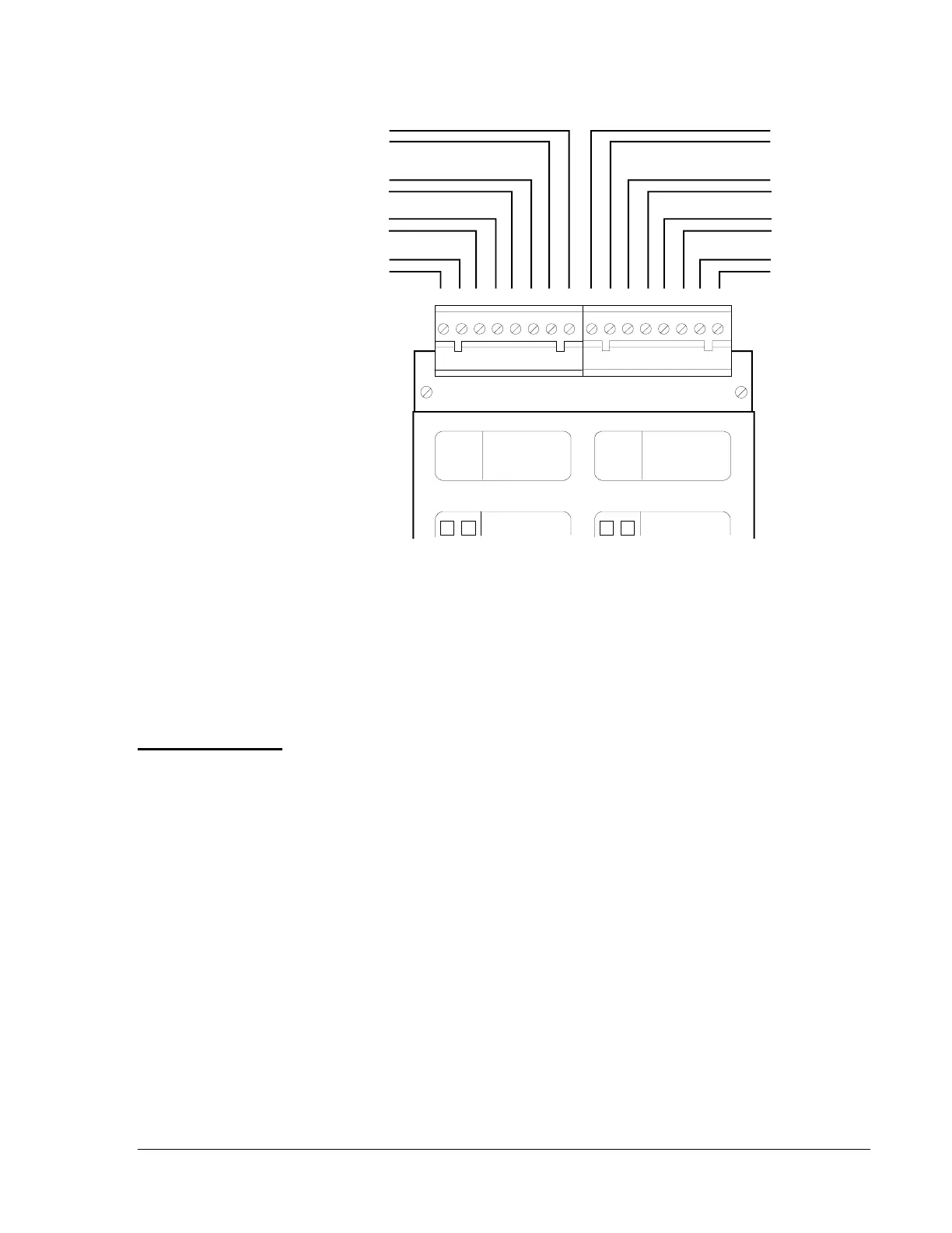
B+ B- B+ B- B+ B- B+ B-
8 7 6 5 4 3 2 116 15 14 13 12 11 10 9
B+ B- B+ B- B+ B- B + B-
All Call
(General
Evacuation)
All Call
Telephone
Page
Telephone
Page
Presignal
Inhibit
Emergency
Alert
Acknowledge
Signal
Silence
Reset
A B C D E F G H
MODULE
TYPE
LAMPS
SWITCH
MODULE
TYPE
LAMPS
SWITCH
IZM-8
Figure 48: Remote Command Input Connections
Notes:
1. Initiating command circuits are supervised, power limited, and may
be connected to limited-energy cable.
2. Maximum line resistance allowed due to wiring is 100 ohms.
● Switches used to control Presignal Inhibit, Acknowledge, Signal
Silence, or System Reset must be key operated, located within a
locked cabinet, or arranged to provide equivalent protection against
unauthorized use.
● Switches must be UL Listed to switch 30 VDC at 50 mA.
● If a key operated switch is used, the key should be removable in both
open and closed positions, when used for Presignal Inhibit. The keys
should be removable in the open position only when used for
Acknowledge, Signal Silence, or System Reset.
● The Presignal Inhibit, Emergency Alert, Acknowledge, Signal
Silence, or System Reset functions can be controlled by a relay
contact from a CRM-4/CRE-4 Relay Module, which can be operated
from switches on ACM-16AT, AEM-16AT, or LDM-32 annunciators.
Remote
Presignal
Inhibit, All Call
(General Alarm),
Emergency
Alert,
Acknowledge,
Signal Silence,
and System
Reset Switches
 Loading...

