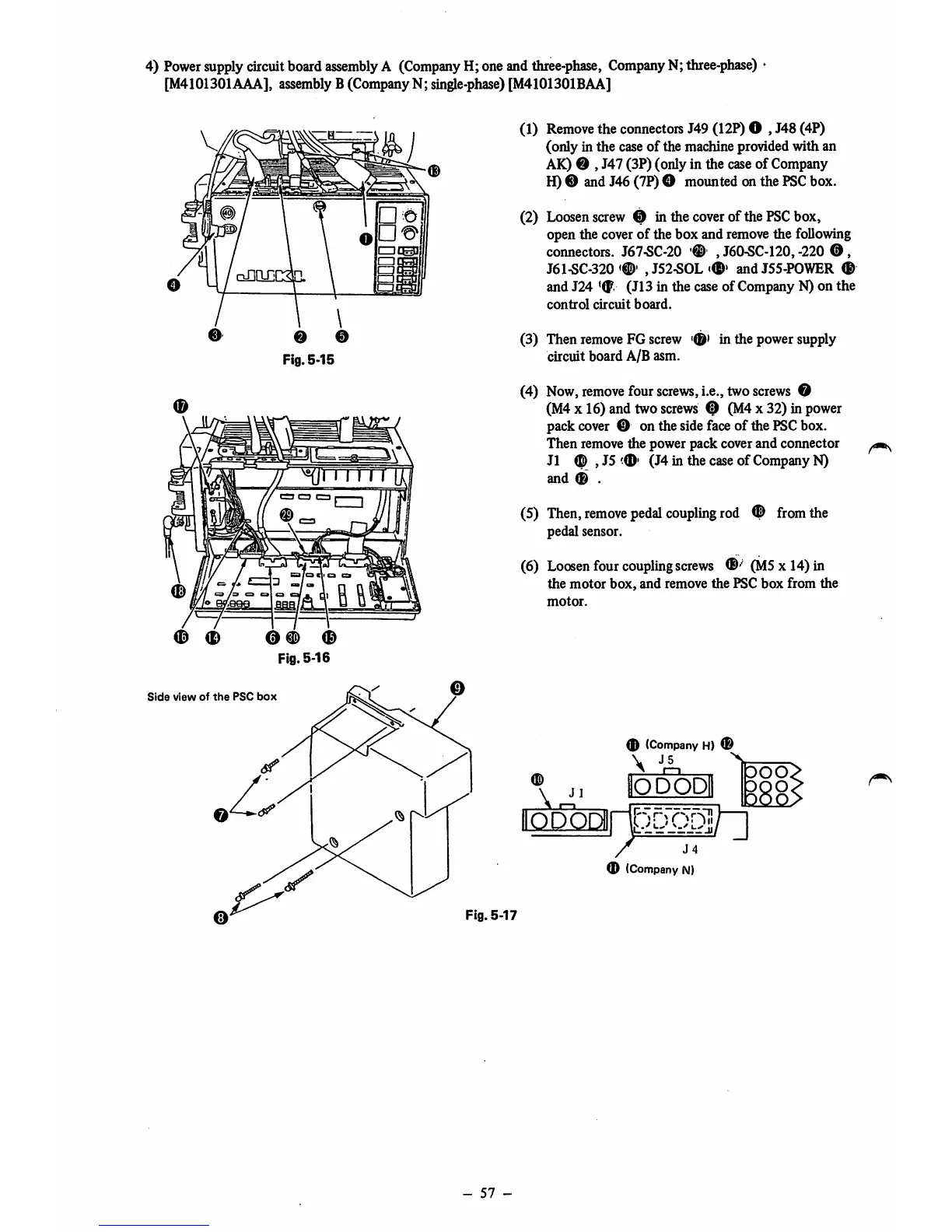
4)
Power
supply
circuit
board
assembly
A
(Company
H;oneand
three-phase,
Company
N;
three-phase)
[M4101301AAA], assembly B(CompanyN;
sing)e-phase)
[M4101301BAA]
Fig.
5-15
0 # 0
Fig.
5-16
Side
view
of
the
PSC
box
(1)
Remove
the
connectors
J49 (12?)O , J48 (4?)
(only in the caseof the machine provided with an
AK) 0 , J47 (3P) (only in the caseof Company
H)® andJ46(7P)O mountedon the
PSC
box.
(2)
Loosen
screw
0 in
the
cover
of
the
PSC
box,
open the coverof the box and removethe following
connectors.
J67-SC-20
, J60-SC-120, -220
®,
J61-SC-320,J52-SOL<®'
andJ55-POWER ®
and J24 '(p. (J13 in the caseof Company N) on the
control
circuit
board.
(3) Then remove FG screw
circuit board A/B asm.
'0'
in
the
power
supply
(4) Now,
remove
four
screws,
i.e., two
screws
O
(M4X16) and two
screws
0 (M4x 32) in power
pack
cover
0 on thesidefaceof the
PSC
box.
Then remove the power pack cover and coimector
J1 (D , J5 (J4 in the caseof CompanyN)
and
0 .
(5)
Then,
remove
pedal
coupling
rod
0
from
the
pedal sensor.
(6) Loosen four couplingscrews (M5 x 14) in
the
motor
box,
and
remove the PSC
box
from
the
motor.
(D
1
®
(Company
H)
®
J5
^
\
aODOD
®
(Company
N)
Fig.
5-17
-
57
-