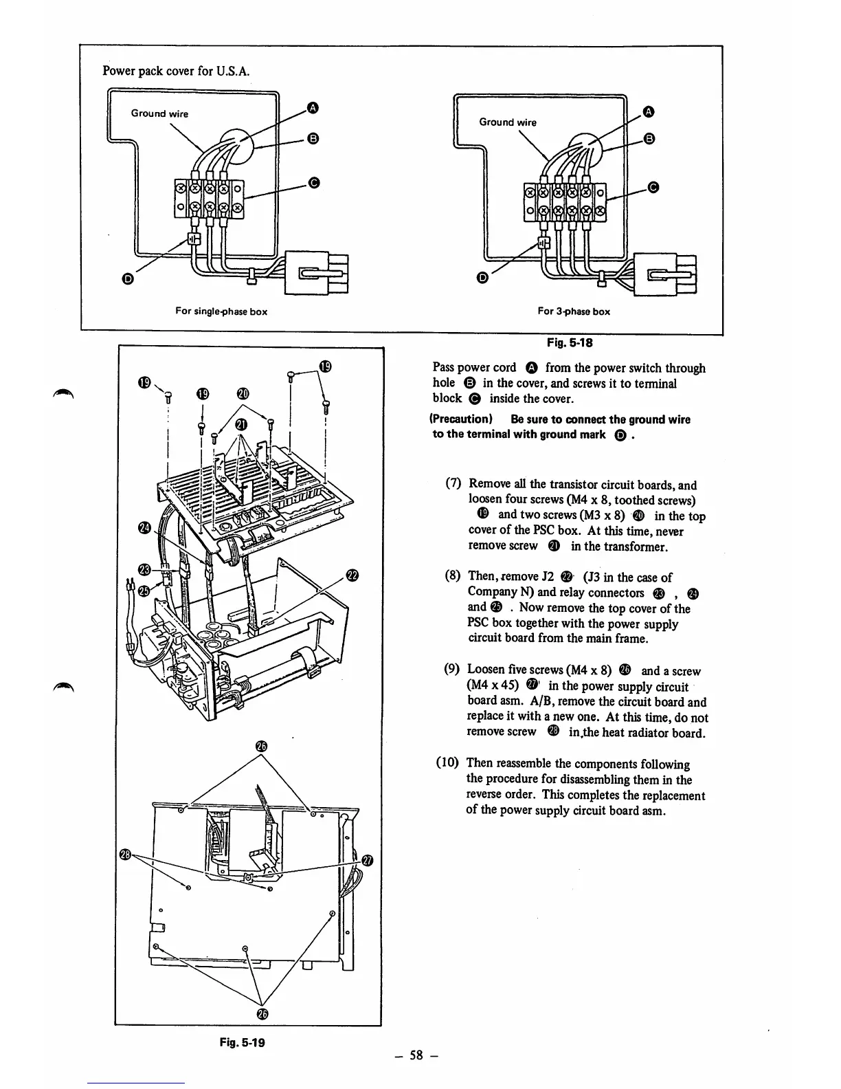
Power pack cover for U.S.A.
Ground
wire
For
single-phase
box
0
0®
m
Fig.
5-19
Ground
wire
For
3-phase
box
Fig.
5-18
Pass
powercord O from the power
switch
through
hole © in the cover, and
screws
it to terminal
block 0 inside the cover.
(Precaution) Besure
to
connect
the
ground wire
to
the
terminal with ground mark 0 .
(7)
Remove
all
the
transistor
circuit
boards,
and
loosen
four
screws
(M4
x 8,
toothed
screws)
0
and
two
screws
(M3
x
8)
0 in
the
top
coverof the
PSC
box. At this time, never
remove screw 0 in
the
transformer.
(8)
Then,
remove
J2 0 (J3 in the
case
of
Company
N)and
relay
connectors 0 , 0
and0
.
Now
remove
thetop
cover
ofthe
PSC
box
together
with
the
power
supply
circuit
board
from
the
main
frame.
(9)
Loosen
five
screws
(M4
x 8) 0 anda
screw
(M4
X
45)
©'
in
the
power
supply
circuit
board asm. A/B, remove the circuit board and
replace
it with a newone. At this time,do not
remove
screw
0 in.theheat radiator board.
(10)
Then
reassemble
the
components
following
the procedure for
disassembling
themin the
reverse
order.
This
completes
the
replacement
of the powersupplycircuitboard
asm.
-
58
-
 Loading...


