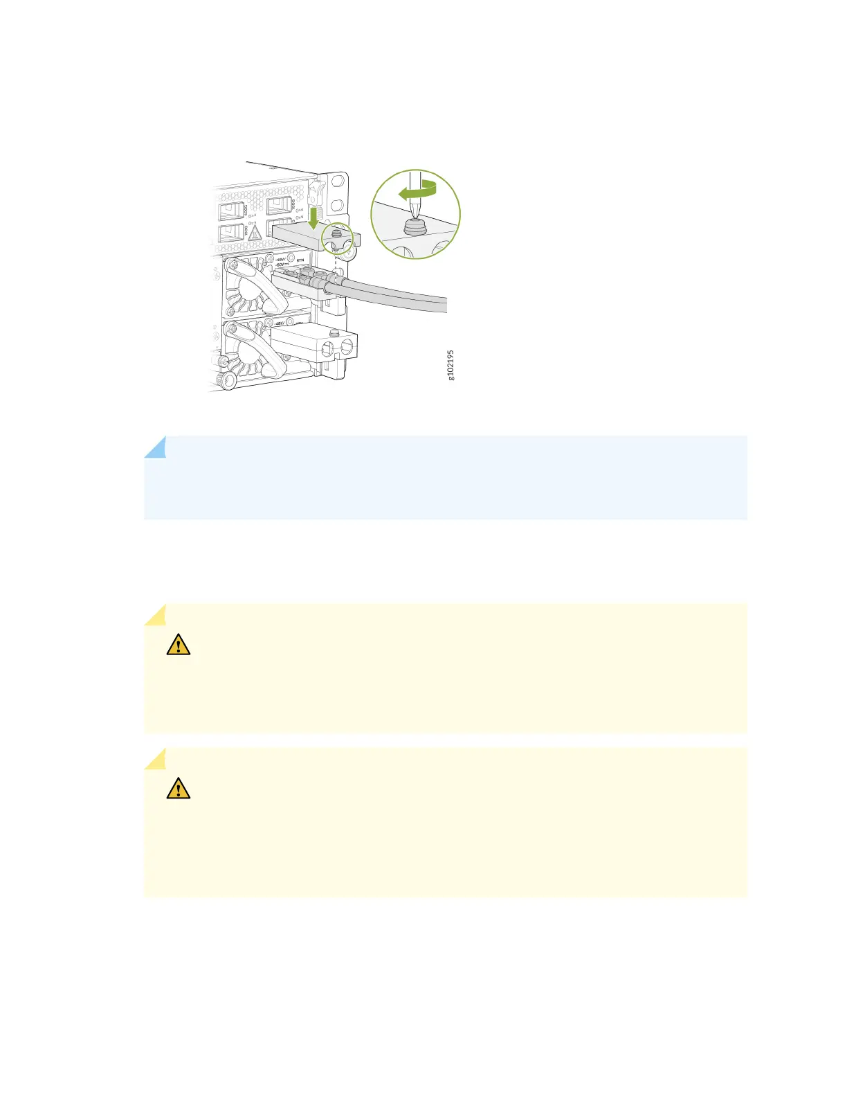
Figure 42: Connecng the DC Cable
NOTE: To connect the DC source to an ACX7348 router, use a 6 AWG and 90 °C
temperature-rated stranded copper wire.
a. Secure the posive (+) DC source power cable lug to the RTN (return) terminal.
b. Secure the negave (–) DC source power cable lug to the –48V/-60V (input) terminal.
CAUTION: Ensure that each power cable lug seats ush against the surface of the
terminal block as you are ghtening the nuts. Ensure that each nut is properly
threaded into the terminal. Applying installaon torque to the nuts when
improperly threaded can result in damage to the terminal.
CAUTION: You must ensure that power connecons maintain the proper polarity.
The power source cables might be labeled (+) and (–) to indicate their polarity.
There is no standard color coding for DC power cables. The color coding used by
the external DC power source at your site determines the color coding for the leads
on the power cables that aach to the terminal studs on each power supply.
8. Place the terminal block cover on and ghten the screw. See Figure 42 on page 86.
9. Verify that the power cables are connected correctly, that they are not touching or blocking access
to router components, and that they do not drape where people could trip on them.
10. Repeat Step 4 through Step 9 for connecng the other PSM to power.
86