Operating mode Automatic cut-in Continuous load
Advantages Fuel saving
Constant oscillation between maximum and
minimum speed avoided
Continuous generator power
available without delay
Tab. 65 Generator operating modes
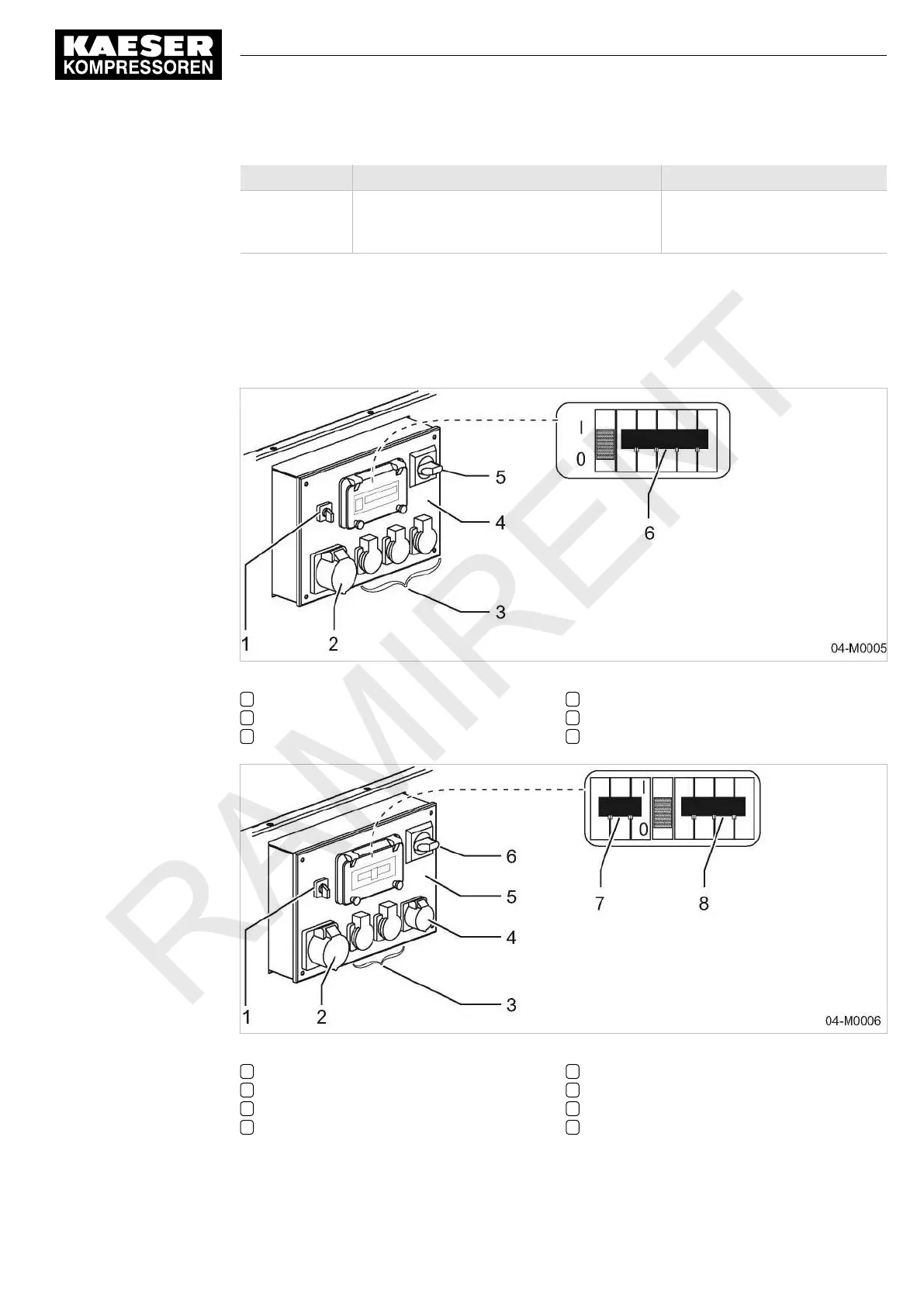
4.6.5.2 Operating controls
The switches, fuses and outlet sockets for electrical consumers are located on the generator con‐
trol box. Individual consumers are connected only by these outlet sockets.
Fig. 13 Instrument panel – generator control box, 400 V AC
1 «Mode selector switch»
2 Three-phase power sockets
3 Single-phase power sockets
4 Generator control box
5 «Generator main switch»
6 «Safety cut-out» (with overcurrent release)
Fig. 14 Instrument panel – generator control box, 230 V AC
1 «Mode selector switch»
2 32 A three-phase power socket
3 Single-phase power sockets
4 16 A three-phase power socket
5 Generator control box
6 «Generator main switch»
7 «Safety cut-out»
8 «Safety cut-out» (with overcurrent release)
4 Design and Function
4.6 Options
No.: 9_5898 26 E
Operator manual Portable compressor
M 64
53