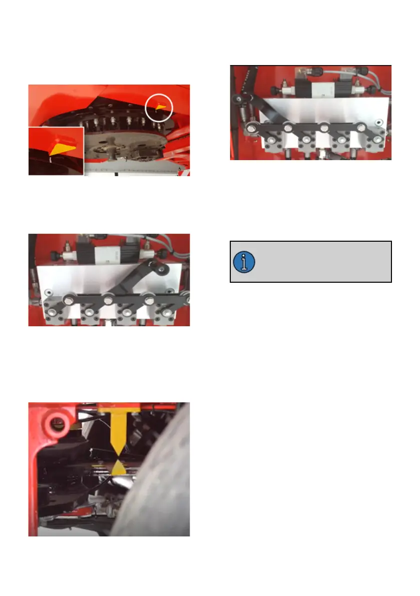
1. First, the gooseneck area should be
aligned with the help of a truck, and it
should be seen that the reference arrow
and the zero line on the table are aligned
as in the picture below.
Alignment of the gooseneck area
2.Lever position on hydraulic valve block
must be set to manual alignment
position.
Location of the manuel alignment of valves
3. The yellow alignment arrows on the
steering hub should be matched by
steering right or left via the remote con-
trol or control panel as in the picture
below.
Yellow alignment arrows
4.The position of the valve levers on the
hydraulic valve block must be taken to
the driving position.
Normal driving position of valves
3.6.2.2. Sensor Calibration
In order for the automatic alignment
function to work correctly in the steering
system, sensor calibrations must be
made.
This operation should defini-
tely be done after the faults in
the steering system are
eliminated.
3.6.2.2.1. Semi-Automatic Alignment
System Proximity Sensor Calibration
In order for the Sensor Calibration to be
correct, the Mechanical Alignment proc-
ess must first be performed.
In the semi-automatic alignment system,
there are 3 proximity sensors in total, 1
on the gooseneck and 2 on the axle
area.
For gooseneck sensor calibration:
Gooseneck alignment arrows must be
matched before starting the calibration
process. The sensor, which is indicated
by 2 in the gooseneck region, is con-
nected to the connection piece in the
structure with the number 1 slot. The
sensor moves left and right in the slot as
seen in the picture. The position where
the sensor sees the 3 bar is defined as
its aligned position. Accordingly, the sen-
sor is positioned at the appropriate place
in the slot, centering the rod.


 To Next Page