31 / 84
Gooseneck sensor calibration
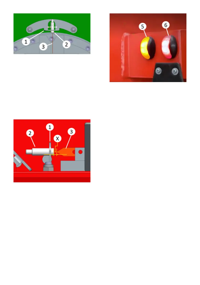
Sensor number 2 can be positioned in-
out as shown in the picture below. The
sensitivity of the system depends on the
distance x between the sensor and the 3
reference bar. As the X distance in-
creases, the system works more sensi-
tively. For this reason, x distance should
be adjusted to a position where the sen-
sor will become passive (the lamp on the
sensor turns off) if the fifth wheel moves
a little to the right or left.
Positioning the sensor in-out
After the alignment in the gooseneck
area is completed, the yellow lamp num-
ber 5, located on the left front of the
gooseneck, should light up according to
the driving direction. This light should go
out with a small movement of the truck to
the right or left. In this way, the goose-
neck region sensor calibration will be
completed.
Lambs
For sensor calibration of axle area:
The steering hub alignment arrows
should line up before starting the calibra-
tion process. In the axle area, the sen-
sors number 1 are con-nected to the
bracket number 2. The bracket is slotted
as in the gooseneck region. The sensors
should be calibrated so that they only
read the number 3 metal part on the
steering hub at one point at a time.
The sensors should be moved from the
outside to the inside (towards the center
of the 2nd bracket) and should be fixed
as soon as they see the metal part. After
the sensors are fixed, one of the sensors
should switch to passive position when
the axles are steered slightly to the right
or slightly to the left. At the same time,
the red lamp number 6 on the gooseneck
should go out. Otherwise, the sensor po-
sitions must be revised again.
Passive state: The lamp on the sensor
goes out
Active state: The lamp on the sensor
lights up


 To Next Page