Instructions for use ELECTROmatic TM and TMM/TMC
4 Installation | 4.4 Installation position 1: Mount below a holder
CAUTION
Damage to the dentist element.
Installations involving an intervention on the treatment unit might damage
components, which can interfere with the safe function and cause injury.
▶ Have installations involving an intervention on the treatment unit per-
formed by trained expert personnel only.
▶ Have the treatment unit subjected to a safety check after installation.
▶ Use the insert holder as a template for the screw positions on the underside
of a holder. If possible, use existing screws or perforations as screw posi-
tions.
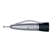
Assembly variant a)
The following parts from the scope of delivery and the installation set are
needed:
▪ 1x Insert holder
▪ 4x Screws M4x12 ④ with self-locking nuts ①
▪ 4x Washers ②
▶ Use 4 screws ④ and 4 washers ② to screw the insert holder to the holder
and fasten it using the 4 nuts ①.
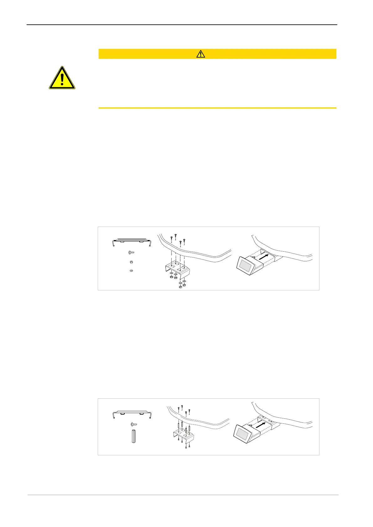
Assembly variant b)
The following parts from the scope of delivery and the installation set are
needed:
▪ 1x Insert holder
▪ 8x Screws M4x12 ④
▪ 4x Spacer bolts, 35 mm ⑦
▶ Use 8 screws to mount the spacer bolts ⑦ or larger commercial spacer bolts
(electronics supplies) between the insert holder and the lower edge of the
holder to increase the distance between the holder and the insert holder, if
applicable.
37 / 90