21
SYSTEM DESCRIPTION
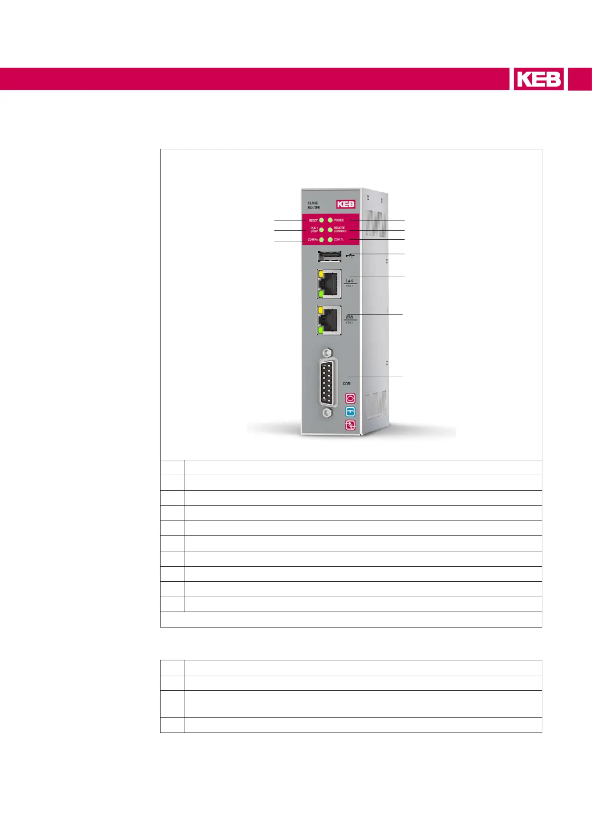
2.3 Front view C6 Router E1 - E4
1
2
3
4
5
6
8
9
7
10
1 Reset LED (yellow)
2 Run /Stop LED (green/red)
3 COM Rx LED
4 COM
5 WAN ETH2
6 LAN ETH1
7 USB
8 COM Tx LED (green)
9 Remote connection LED (green)
10 Power LED (green)
Figure 2: Front detail
Thefollowingbehaviorsaredened:
• Steady lighted
• Blinking
• Continuous sequence of a blink codes with a short pause in between to report
a status.
• Single sequence of a blink code to report an event.
 Loading...


