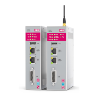
43
INSTALLATION AND CONNECTION
3.10 Connecting the device
3.10.1 Notes on connection
• COMBIVIS connect Router device must be installed in accordance with the indi-
cations contained in this instruction manual.
• These devices are intended to be connected to a “Secondary Circuit Overvoltage
Category II”.
3.10.2 Grounding and bonding
Whenever two pieces of equipment connected to each other are far apart, it is possible
that their ground connections could be at a dierent potential level. The shielding of
the data cable connects the machine housing on one end and the COMBIVIS connect
Router device housing on the other end and is therefore subject to high compensation
currents that can destroy the interface. To overcome this hazard such current must be
steered away from the interface. To achieve this goal the following methods can be used:
• Use an equipotential bonding cable (16mm
2
, suitable at least 75C°) to connect the
equipment’s’ ground to the COMBIVIS connect Router device’s ground.
• Connect the shielding of the data cable at both ends to the equipotential bonding
rail before connecting the interfaces.
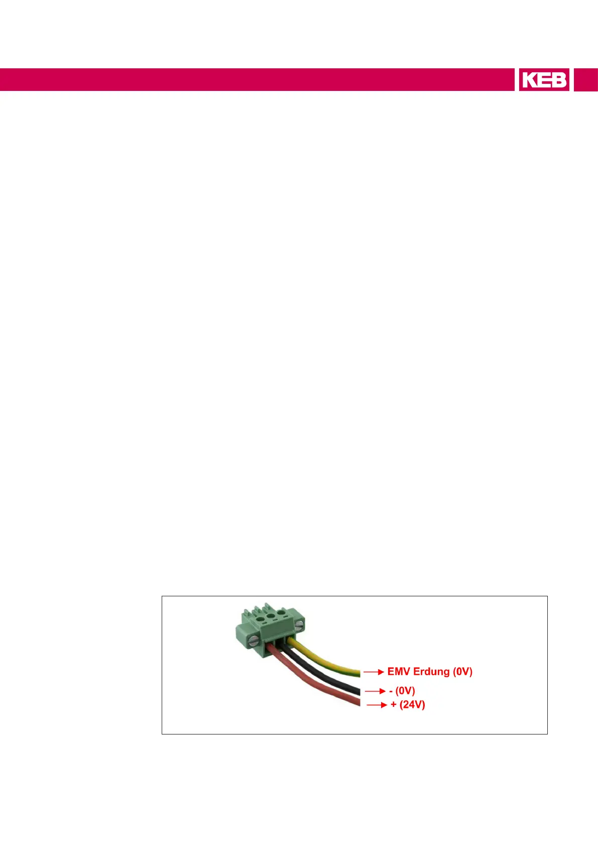
3.10.3 Power supply connection
The device may only be connected to a 12V or 24V power supply (maximum permissi-
bleoperatingvoltagerange9Vto36V)whichfulllstherequirementsofsafeextralow
voltage (SELV) in accordance with IEC/EN/DIN EN/UL60950-1.
ThepowersupplyhastofulltherequirementsNECClass2orLPSinaccordancewith
IEC/EN/DIN EN/UL60950-1Connect the device with a cable cross-section of 0.75 – 1.5
mm2 (AWG18 to AWG16 suitable at least 75C°).
• Remove the three poles connector from the system.
• Connect the positive pole, the negative and the ground one (also refer to the label
on the back of the system) to the related terminals of the three pole connector.
 Loading...


