6 3
KEB COMBIVERT F4-F
10
Name: Basis
02.03.99
Chapter Section Page Date
© KEB Antriebstechnik, 1999
All Rights reserved
Functional Description Digital In- and Outputs
OUT 3
8
11 23
D1
0V U
ext
X2
9
11 23
D2
0V
U
ext
X2
20
21 22
RLA
RLB
RLC
X2
max. 30V / 1A DC
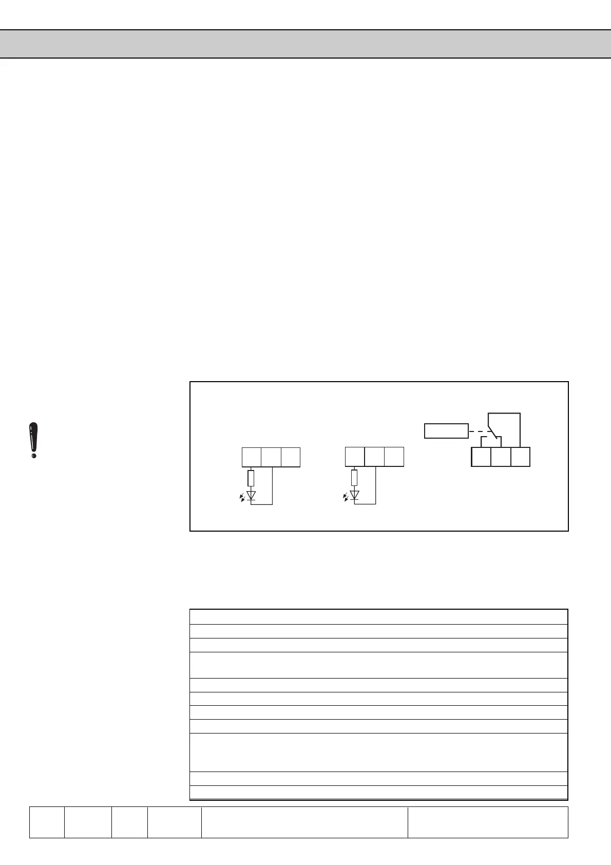
The KEB COMBIVERT F4-F has
- 2 transistor outputs Out D1 terminal X2.8
Out D1 terminal X2.9
- 1 relay output Out3 terminal X2.20/ X1.21/ X1.22(RLA, RLB, RLC)
- 4 internal outputs OUT A...D (firmly connected with the inputs A...ID)
For the switching of the digital outputs you can select up to 8 conditions from the 33
condtions available. These are entered in do.1...do.8. Parameter ru.17 indicates
whether one or several of these conditions are met. For each output you can now
choose which of the 8 conditions shall apply to it (do.9...do.16). You can either select
no condition or all eight. 2 of the conditions can be filtered by means of the digital
output filters. Each of the conditions can still be inverted prior to selection
(do.17...do.24). As a standard all conditions (if several are selected) are OR-operated,
i.e. if one of the selected conditions is fulfilled the output switches. This can be changed
to an AND-operation by means of do.25, i.e. all of the selected conditions must be
fulfilled before the output is set. Parameter do.0 serves to negate one or several
outputs. Parameter ru.15 shows if the output is switched real or through negating.
The internal outputs Out A...D are connected directly with the internal inputs IA...ID
(see Fig. 6.3.1).
6.3.11 Output Signals
Fig. 6.3.11 Connection of digital outputs
6.3.12 Switching
Conditions
(do.1...do.8)
Up to 8 of the following switching conditions can be selected for further processing.
The values are then entered in the parameter do.1...do.8.
Value Function
0 generally disabled
1 generally enabled
2 Availability signal, initalization completed, no fault or abnormal
operating status exists
3 Run signal, inverter is ready for operation and modulation is release
4 Abnormal operating state at „abnormal stopping“
5 Fault signal, modulation is blocked after fault or fast stop
6 - reserved -
7 PTC-warning, upon tripping of the motor-PTC connected to the terminals
OH/OH. After expiration of an adjustable switch-off time Pn.16 (0...120s)
the inverter triggers the error E.dOH
8 - reserved -
9 *1 Current controller in the limit (max. output voltage reached)
A current of 20mA shall be
taken from each transistor
output X2.8 and X2.9.
In case of inductive loads on
the relay output or the
transistor outputs a protective
circuit must be provided (free-
wheeling diode)!

 Loading...
