6 9
KEB COMBIVERT F4-F
4
Name: Basis
09.08.00
Chapter
Section
Page Date
© KEB Antriebstechnik, 1999
All Rights reserved
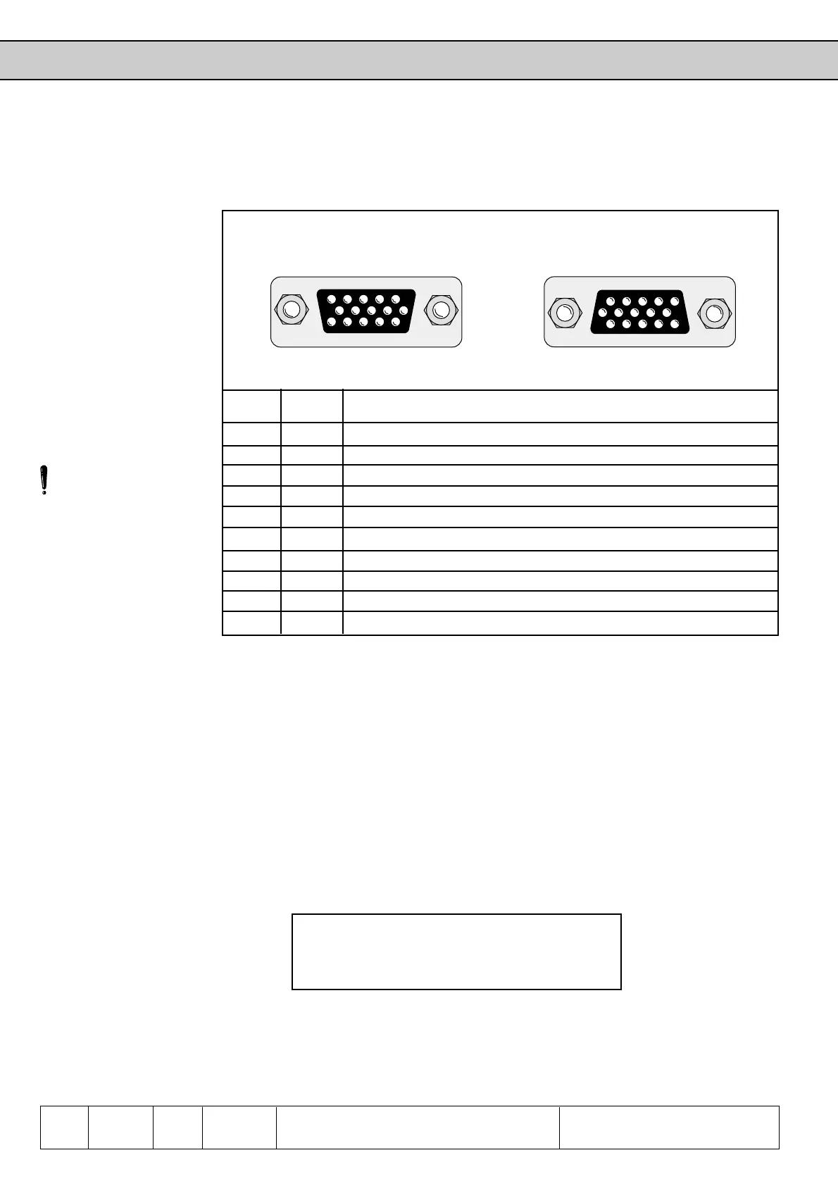
Functional Description Encoder Interface
12345
678910
11 12 13 14 15
54321
10 9 8 7 6
15 14 13 12 11
6.9.2 Encoder
Interface
Channel 1
(X4)
Fig. 6.9.2 Encoder interface channel 1 (X4)
Signal X4 Description
U
var
11 Supply voltage for encoder
+5 V 12 Supply voltage for encoder
0 V 13 Reference potential
A 8 Signal input A
_
A 3 Signal input A inverted
B 9 Signal input B
_
B 4 Signal input B inverted
N 15 Reference marking input N
_
N 14 Reference marking input N inverted
Shield Housing Shielding
U
var
is an unstabilized voltage that is provided by the power stage of the KEB COMBIVERT.
Dependent on the size of unit and the load, the voltage amounted to 15... 30 V DC (see
chapter 6.9.6). Uvar is loadable at X4 and X5 with altogether 110 mA. If higher voltages /
currents to supply the encoders are needed then the control must be supplied with an external
voltage.
The +5 V voltage is a stabilized voltage and loadable at X4 and X5 with altogether 300 mA.
The signal and reference marking inputs can be triggered with rectangular pulses as well as
sine-wave signals. The signal inputs must generally be connected. The reference marking
singals are only needed for the reference point approach in the positioning operation.
Following specifications apply to the encoder interface 1 (X4):
• max. operating frequency of input f
G
= 200 kHz
• internal terminating resistor R
t
= 150 Ω
• 2…5 V high level at rectangular signals
• U
0
= 2,5 V and 1 Vss at sine / cosine signals
U
var
as of housing size G up to housing size E
Pin description
Inputs
Only when the inverter is
switched off and the
voltage supply is
disconnected may the plug
be pulled out or plugged in!
Concerning encoder inputs with HTL-level please contact KEB.
The encoder interface 1 is the connection for the speed feedback of the KEB COMBIVERT
F4-F, which is imperative for the entire control (current control, too).
+5V

 Loading...
