5
ANTRIEBSTECHNIK
69 5
KEB COMBIVERT F4-F
Name: Basis
09.08.00
6
Section PageDate
© KEB Antriebstechnik, 1999
All Rights reserved
Chapter
Functional DesriptionEncoder Interface
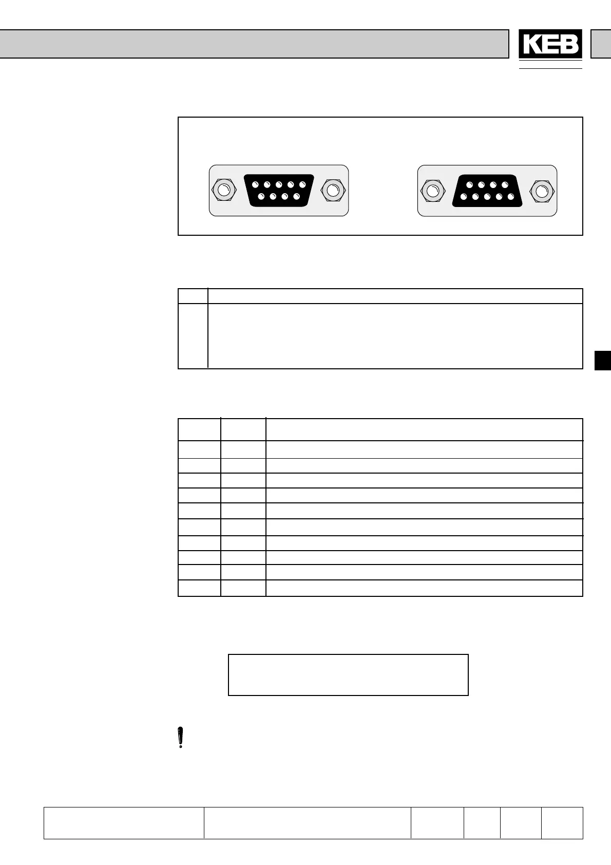
6.9.3 Encoder
Interface
Channel 2
(X5)
Fig. 6.9.3 Encoder interface channel 2 (X5)
as of housing size G up to housing size E
12345
6789
54321
9876
In.57 Definition of the
interface
Channel 2 can be equipped with different interfaces. To avoid the connection of a wrong
encoder, the installed interface is indicated in In.57.
In.57 Encoder Interface 2
0 Incremental encoder input
1 Synchron-serielles Interface (SSI)
4 Incremental encoder output, the input signals of channel 1 are given out on
channel 2
7 Between incremental endocer input and output switch-selectable interface
Incremental encoder
input
Signal X5 Description
U
var
5 Supply voltage for encoder (see 6.9.2)
+5 V 4 Supply voltage for encoder (see 6.9.2)
0 V 9 Reference potential
A 1 Signal input A
_
A 6 Signal input A inverted
B 2 Signal input B
_
B 7 Signal input B inverted
N 3 Reference marking input N
_
N 8 Reference marking input N inverted
Shield Housing Shielding
In synchronous operation the second incremental encoder serves as input of the master
drive. A second position encoder can be connected for positioning operation.
The signal inputs of the second encoder interface support only rectangular signals.
Following specifications apply to the endocer interface 2 (X5):
• max. operating frequency of input f
G
= 300 kHz
• internal terminating resistor R
t
= 150 Ω
• 2…5 V high level at rectangular signals
Only when the inverter is switched off and the voltage supply is disconnected may the
plug be pulled out or plugged in !

 Loading...
