3
ANTRIEBSTECHNIK
69 3
KEB COMBIVERT F4-F
Name: Basis
09.08.00
6
Section PageDate
© KEB Antriebstechnik, 1999
All Rights reserved
Chapter
Functional DesriptionEncoder Interface
S
T
A
R
T
S
T
O
P
E
N
T
E
R
F
/R
F
U
N
C
.
S
P
E
E
D
START
STOP
ENTER
F/R
FUNC.
SPEED
Î
Î
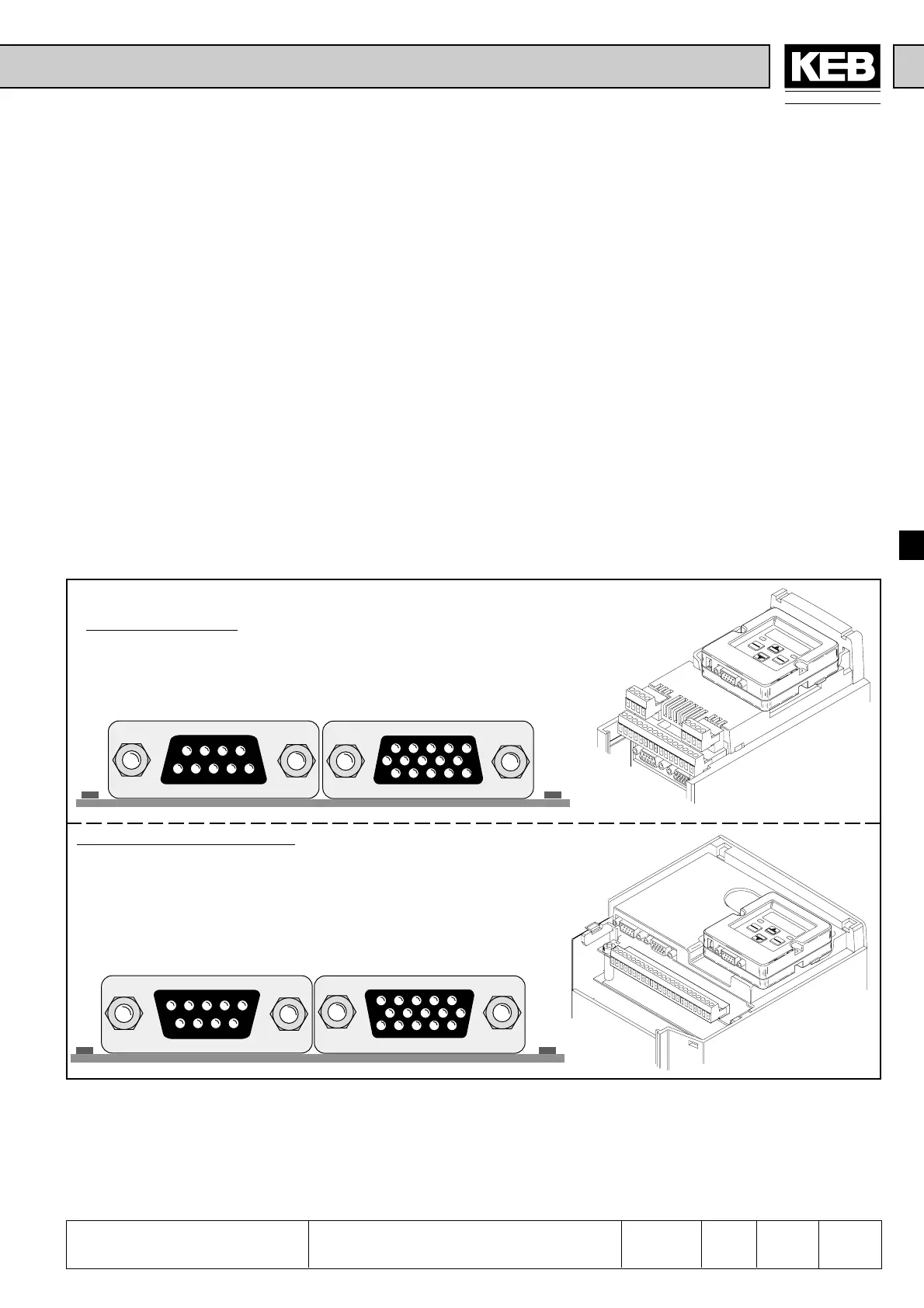
6.9 Encoder Interface
6.9.1 Designs
The KEB COMBIVERT F4-F supports two from each other separated encoder
channels.
Channel 1 (X4)
• is an incremental encoder input for sine-wave 1Vss- or rectangular signals
Channel 2 (X5)
• is an incremental encoder input and/or output for rectangular singals
Fig. 6.9.1 Encoder survey
from housing size G upwards
up to housing size E
Depending on the housing size two different encoder interfaces are used (see below).
At that the first encoder interface (X4) represents the standard, the second encoder
interface (X5) can be built-in in following designs:
• incremental encoder input
• incremental encoder output
• incremental encoder in-/output
12345
678910
11 12 13 14 15
12345
6789
X5 X4
54
3
21
9876
54321
9876
54321
10 9 8 7 6
15 14 13 12 11
X5 X4

 Loading...
