6 11
KEB COMBIVERT F4-F
12
Name: Basis
17.06.99
Chapter
Section Page Date
© KEB Antriebstechnik, 1999
All Rights reserved
Functional Description Positioning Module
Reference point mode
(Pc.10)
This parameter defines how the reference point approach is started or stopped.
• Reference point approach by Pd.1 or digital input (Pc.10 =0, 2, 4)
• Reference point approach with the first „Start positioning“ - command
(Pc.10 =1, 3 or 5) after restart of the inverter (power on or changing of Pc.0).
The difference exists in the behaviour of the drive after reaching the reference point:
Pc.10 Function
0 and 1 After reaching the reference point the drive runs to the reference marking of the
encoder. If the reference marking was not yet approached (starting reference
point approach shortly before reference point switch) then the drive continues to
run to the limit switch, reverses and starts a new approach of the reference point.
2 and 3 Drive stops after reaching the reference point.
4 and 5 Like value „0“, but the error E.EnC is triggered if no reference marking signal
exists (e.g. track N not connected)
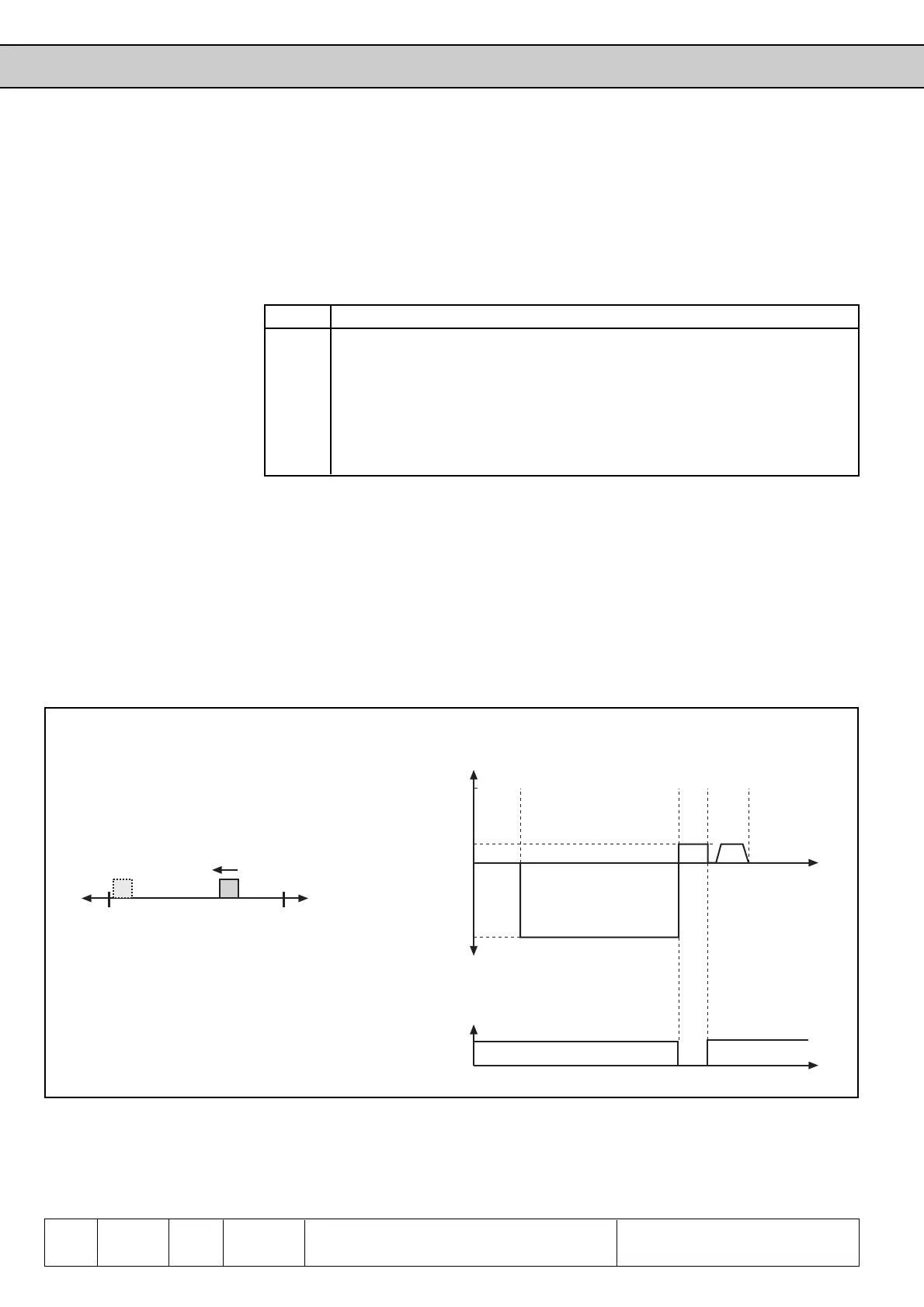
One limit switch serves at the same time as reference point switch; reference point run with
approach of reference marking of encoder.
• Terminal X2.3 = limit switch right (di.11 = 16)
• Terminal X2.4 = limit switch left + reference point switch (di.12 = 21)
• Reference speed -100 min
-1
with counter-clockwise rotation (Pc.14 = -100)
• Starting of reference point approach with X2.7 (di.5 = 10) or by bus / PC with
parameter Pd.1 = 2 (Pc.10 = 0)
6.11.16 Reference
Point
Approach
Examples
X2.4 X2.3
v
REF
12
+v
REF
-v
REF
t
Pc.14
Pc.14
0,25xPc.14
ABCD
t
0
1
X2.4
A: Starting reference point approach
B: Brought in position at reference switch
C: Reference switch cleared
D: Reference marking of encoder reached
1: Original position
2: Position after reference point approach
Fig. 6.11.15 Reference point approach example 1

 Loading...
