6 3
KEB COMBIVERT F4-F
12
Name: Basis
02.03.99
Chapter Section Page Date
© KEB Antriebstechnik, 1999
All Rights reserved
Functional Description Digital In- and Outputs
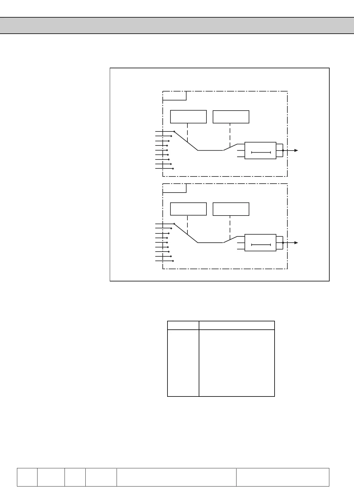
6.3.13 Output Filter Unit
(do.26...do.31)
t
do.28
do.26
do.30
do.1
do.2
do.3
do.4
do.5
do.6
do.7
do.8
off
0
1
2
0
8
t
do.29
do.27
do.31
do.1
do.2
do.3
do.4
do.5
do.6
do.7
do.8
off
0
1
2
0
8
Fig. 6.3.13 Function chart of output filters
The output filter unit consists of two digital filters independent of each other. Each of
the filter can be assigned to any selected switching condition.
Logic operation of
output filters
(do.30, do.31)
For that the parameters do.30 and/or do.31 are adjusted to the condition to be filtered
as follows:
Value Function of do.30 / do.31
0 none
1 switching condition 1 (do.1)
2 switching condition 2 (do.2)
3 switching condition 3 (do.3)
4 switching condition 4 (do.4)
5 switching condition 5 (do.5)
6 switching codnition 6 (do.6)
7 switching condition 7 (do.7)
8 switching condition 8 (do.8)
Filter time
(do.28, do.29)
The entered value defines the time with which, depending on the selected mode, the
evaluation is done (see example) The filter time is calculated as follows:
Adjusted value (0...488) * scan time (2,048ms) = 0...999ms
In COMBIVIS the input is done directly in ms and is rounded off accordingly.
Filter 1
Choice
Filtermode
Filter 2
Choice
Filtermode

 Loading...
