6 10
KEB COMBIVERT F4-F
6
Name: Basis
15.03.99
Chapter
Section Page Date
© KEB Antriebstechnik, 1999
All Rights reserved
Functional Description Sychronous Control
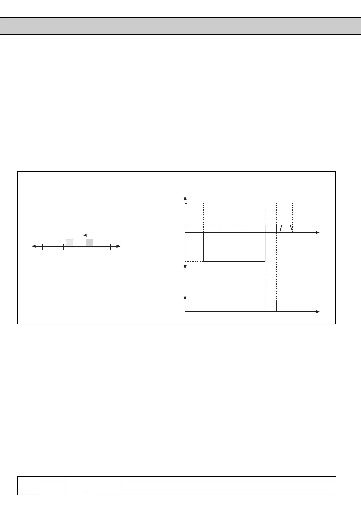
With two limit switches and one reference point switch; reference point run with approach
of the reference marking of the encoder.
• Terminal X2.3 = limit switch right (di.11 = 16)
• Terminal X2.4 = limit switch left (di.12 = 17)
• Terminal X2.5 = reference point switch (di.3 = 12)
• Reference speed -100 min
-1
with counter-clockwise rotation (Pc.14 = -100)
• Starting of reference point approach with X1.7 (di.5 = 10) or by bus / PC with
parameter Pd.1 = 2 (Pc.10 = 0)
If the zero pulse shall not be approached (Pc.10 = 2), then only the reference point switch
is cleared and the drive stops then.
Example 2
X2.4 X2.3
v
REF
12
X2.5
+v
REF
-v
REF
t
Pc.14
Pc.14
0,25xPc.14
ABCD
t
0
1
X2.5
A: Starting reference point approach
B: Brought in position at reference switch
C: Reference switch cleared
D: Reference marking of encoder reached
1: Original positioning
2: Position after reference point approach
Fig. 6.10.7.a Reference point approach example 2

 Loading...
