5
ANTRIEBSTECHNIK
10 1 5KEB COMBIVERT F4-F
Name: Basis
22.12.98
10
Project Planning
Section PageDate
© KEB Antriebstechnik, 1998
All Rights reserved
Chapter
( )
(J
M
+ J
L
) • (n
1
- n
2
)
t
Bmin
=
9,55 • (K • M
N
+ M
L
)
1. Braking time without braking resistor 2. Braking torque (necessary)
4. Braking time with braking resistor
Formula
Valid range: n
1
> n
N
(Field weakening range)
Condition: M
B
< 1.5 • M
N
f < 70 Hz
Condition: P
B
< P
R
Valid range: n
1
> n
N
P
R
• 9,55
Condition:
< M
N
• (1,5 -K)
(n
1
- n
2
)
f < 70 Hz
P
B
< P
R
J
M
= mass moment of inertia motor [kgm
2
]
J
L
= mass moment of inertia load [kgm
2
]
n
1
= motor speed prior to deceleration [min
-1
]
n
2
= motor speed after deceleration [min
-1
]
(standstill= 0 min
-1
)
n
N
= rated motor speed [min
-1
]
M
N
= rated motor torque [Nm]
M
B
= braking torque (necessary) [Nm]
M
L
= load torque [Nm]
t
B
= braking time (necessary) [s]
t
Bmin
= minimum braking time [s]
t
Z
= cycle time [s]
P
B
= peak braking power [W]
P
R
= peak power of braking resistor [W]
(J
M
+ J
L
) • (n
1
- n
2
)
M
B
= - M
L
9,55 • t
B
M
B
• n
1
P
B
=
9,55
3. Peak braking power
(J
M
+ J
L
) • (n
1
- n
2
)
t
Bmin
* =
P
R
• 9,55
9,55 • K• M
N
+ M
L
+
(n
1
- n
2
)
Cyclic duration factor (cdf)
t
B
cdf = • 100 %
120 s
Cyclic duration factor for cycle time t
Z
> 120 s
t
B
cdf = • 100 %
t
Z
Cyclic duration factor for cycle time t
Z
< 120 s
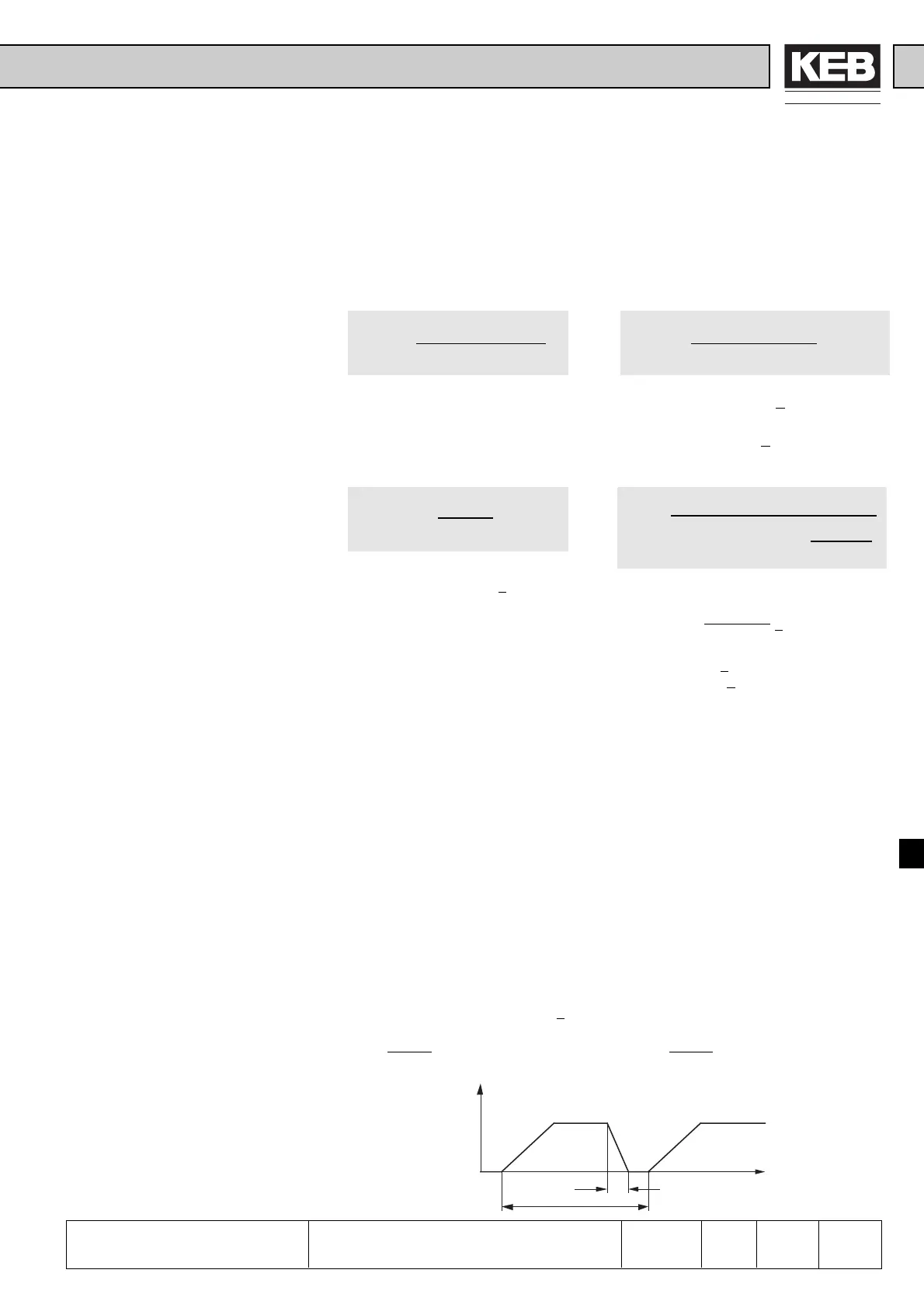
t
f
t
B
t
Z
Braking time DEC
The braking time DEC is adjusted at the frequency inverter. If it is chosen too
small the KEB COMBIVERT switches off automatically and the error message
OP or OC appears. The approximate braking time can be determined according
to following formulae.
K = 0,25 for motors up to 1,5 kW
0,20 for motors 2,2 to 4 kW
0,15 for motors 5,5 to 11 kW
0,08 for motors 15 to 45 kW
0,05 for motors 55 to 75 kW

 Loading...
