ANTRIEBSTECHNIK
3
15
KEB COMBIVERT F4-F
Name: Basis
02.02.99
3
Section PageDate
© KEB Antriebstechnik, 1999
All Rights reserved
Chapter
HardwareControl Cards
20 22 23
1234
21
16 17 185 6789101112131415 19
123456789101112
13 14 15 16 17 18 19 20 21 22 23
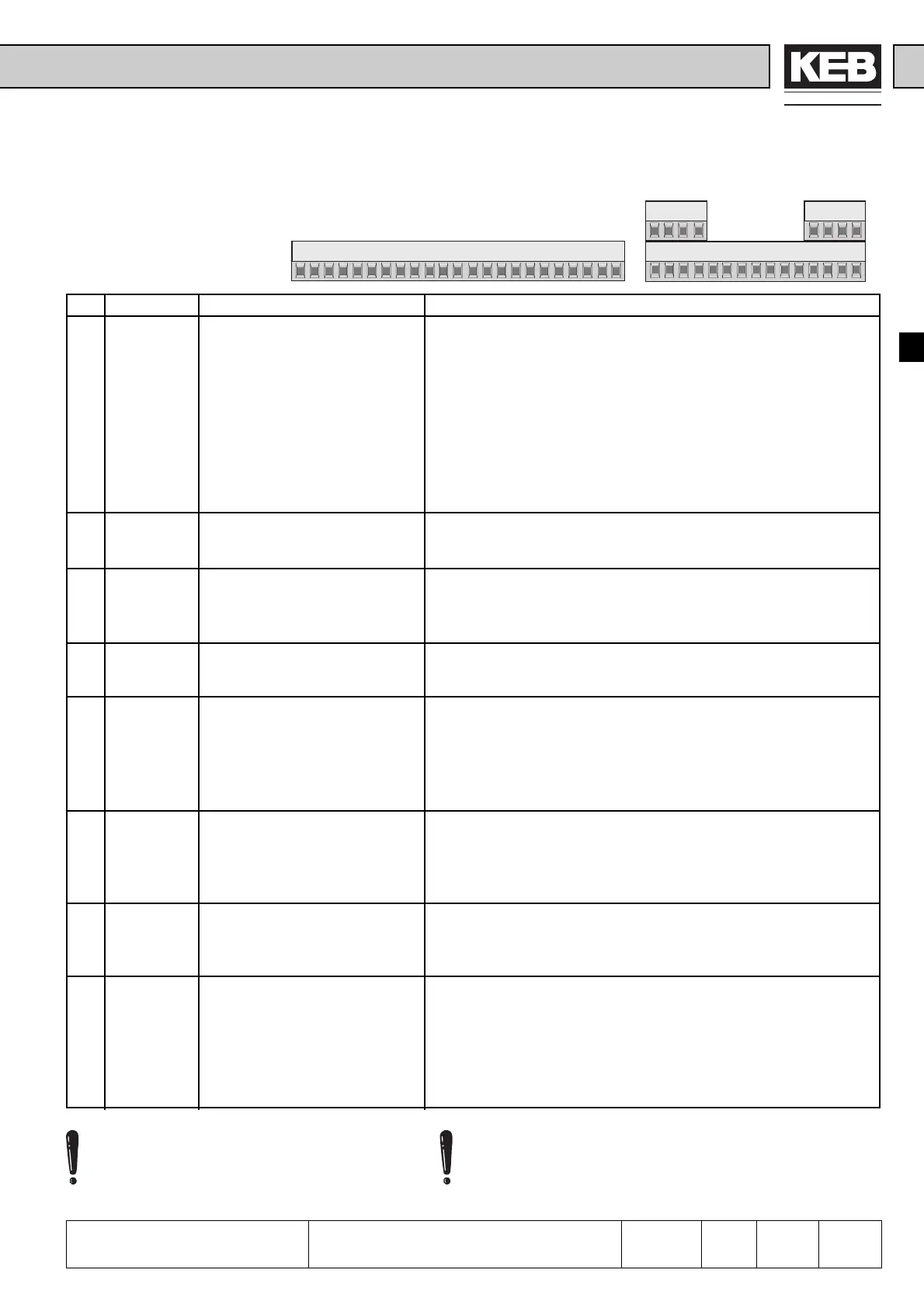
3.1.3 Control Terminal
Strip X2
for housing size D and Efrom housing size G upwards
Ter. Name
1ST
2I4
3I5
4I6
5I1
6I2
7I3
8D1
9D2
10 Uout
11 0V
12 CRF
13 COM
14 REF 1 +
15 REF 1 -
16 REF 2 +
17 REF 2 -
18 A1
19 A2
20 RLA
21 RLB
22 RLC
23 Ext. Spg.
Function
Control release
Reset
Rotation selection / forward
*1
Rotation selection / reverse
*1
Programmable input 1
(Jog-speed forward
*1
)
Programmable input 2
(Jog-speed reverse
*1
)
Programmable input 3
(external fault
*1
)
Digital output 1 (Out 1)
Digital output 2 (Out 2)
Voltage output
Mass for Uout and
digital in-/outputs
+10 V reference voltage
Analogmass
Analog setpoint input
see An.2 - An.5 (chapter 5.9)
Prog. analog input
see An.8 - An.11 (chapter 5.9)
Analog output 1
Analog output 2
Output relay
(Out 3)
External voltage supply
Digital Inputs
logic 1: ± (12...30V)
internal input resistor: approx. 2 kΩ
Logic: PNP/NPN (prog. with di.1 )
(*1)
Factory setting, also other functions can be assigned to the
terminals (see chapter 6.3 „Digital inputs“)
Scan time: 2ms
programmable PNP-transistor outputs 14…30 V / max. 20 mA
per output (see chapter 6.3 „Digital In- and Outputs“)
Voltage output: supply voltage provided by the inverter for digital
in- and outputs
Voltage:depending on power circuit and load 16…30 V max.60 mA
Voltage output: +10V (+/-3%); max. 4 mA
Mass for analog in-/outputs
Differential voltage input
±10 V / resolution: 12 Bit / Ri = 24 kΩ / 40 kΩ (see next page)
Current inputs can only be realized by external switch mode with
load resistance (see chapter 6.2). Scan time: 2ms / At fast setpoint
input and torque control: 128µs
Analog outputs
Voltage range: 0...±10V / internal resistance: 100 Ω
Resolution: 10 bit (see chapter 6.2 „Analog outputs“)
Scan time: 2ms
30 VDC / 1A
(see chapter 6.3 „Digital In- and Outputs“)
External voltage input: Bezugspotential 0V (X2.11) external
supply voltage for digital in-/outputs (only necessary if the voltage
provided by the inverter is too low for a primary control or an ex-
ternal encoder) and for the supply of the control card at switched
off power circuit (this function is not available for all power
circuit sizes)
Potential isolation between terminals for digi-
tal signals (X2.1 - X2.11, X2.23) and terminals
for analog signals (X2.12 - X2.19).
Release of rotation (X2.3 / X2.4) and torque limitation (prog.
funktion for analog input 2 (X2.16 / X2.17)) do not have a
function in the Drive-Mode (see chapter 4.4).

 Loading...
