E 20
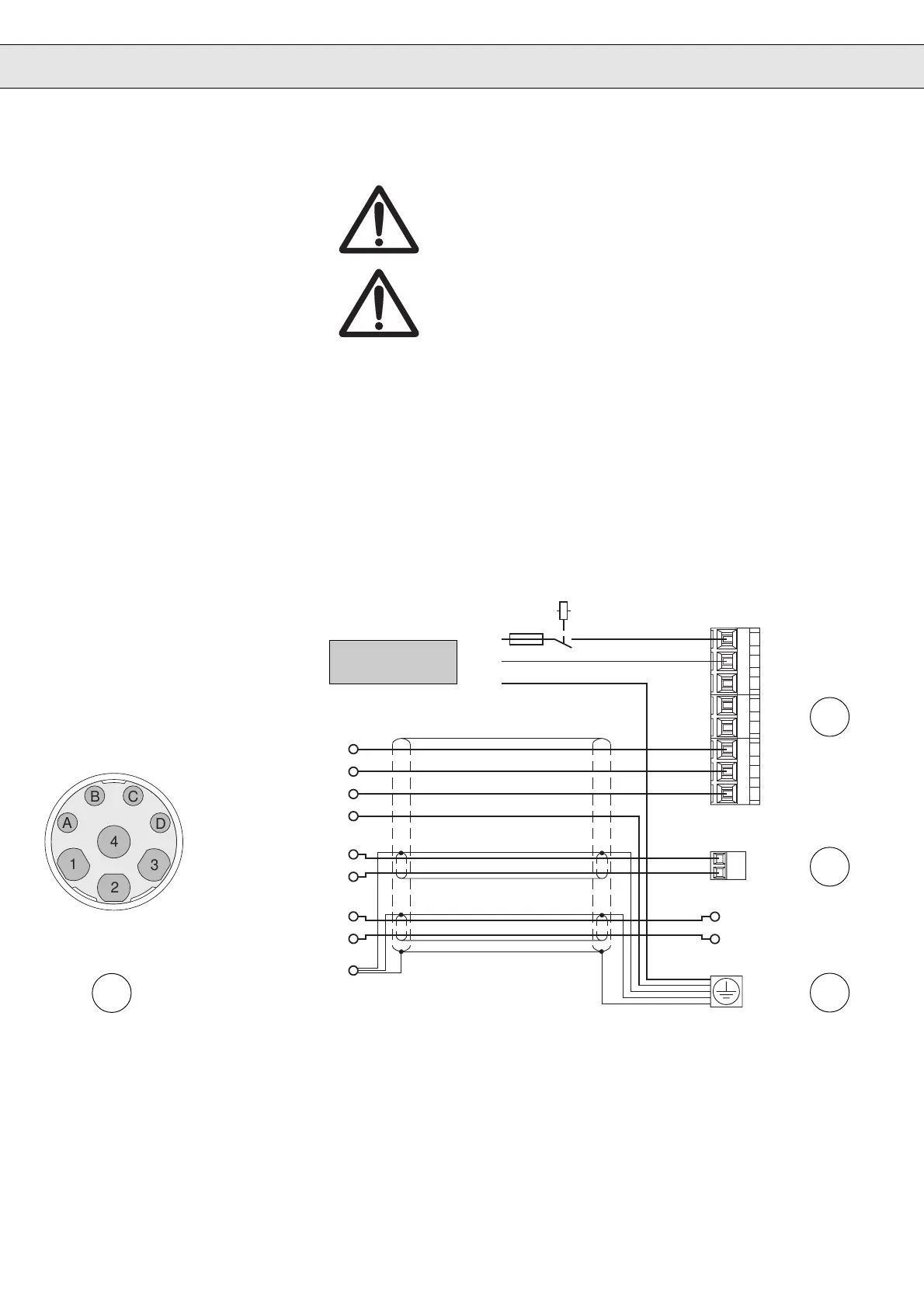
6.2 1-phase Connection
230 V Class
Remove or plug in the power connector only at switched off
unit and disconnected power supply !
Observe the correct phase sequence for the connection of
the servo motor !
6. Connection
}
PTC-connection
PTC-connection
Brake +
Brake –
C
D
A
B
A
B
C
D
1
2
3
4
U
V
W
PE
1
4
3
2
L1
L2
L3
PA
PB
U
V
W
OH
OH
L1
N
PE
Mains connection
6
7
9
8
PE Protective earth conductor
U, V, W Motor
L1, L2 Mains connection 1-phase
PA, PB Connection braking resistor
Servo motor
power connector
Motor housing/
threaded joint
Connect extensive
shield to both sides!
External brake supply
unit with own voltage
supply
Connector Cable
Contact No. Designation Core No.
1U1
4V2
3W3
2 PE Green-Yellow
A Brake + 5
B Brake – 6
C PTC-Contact 7
D PTC-Contact 8

 Loading...


