E 21
ANTRIEBSTECHNIK
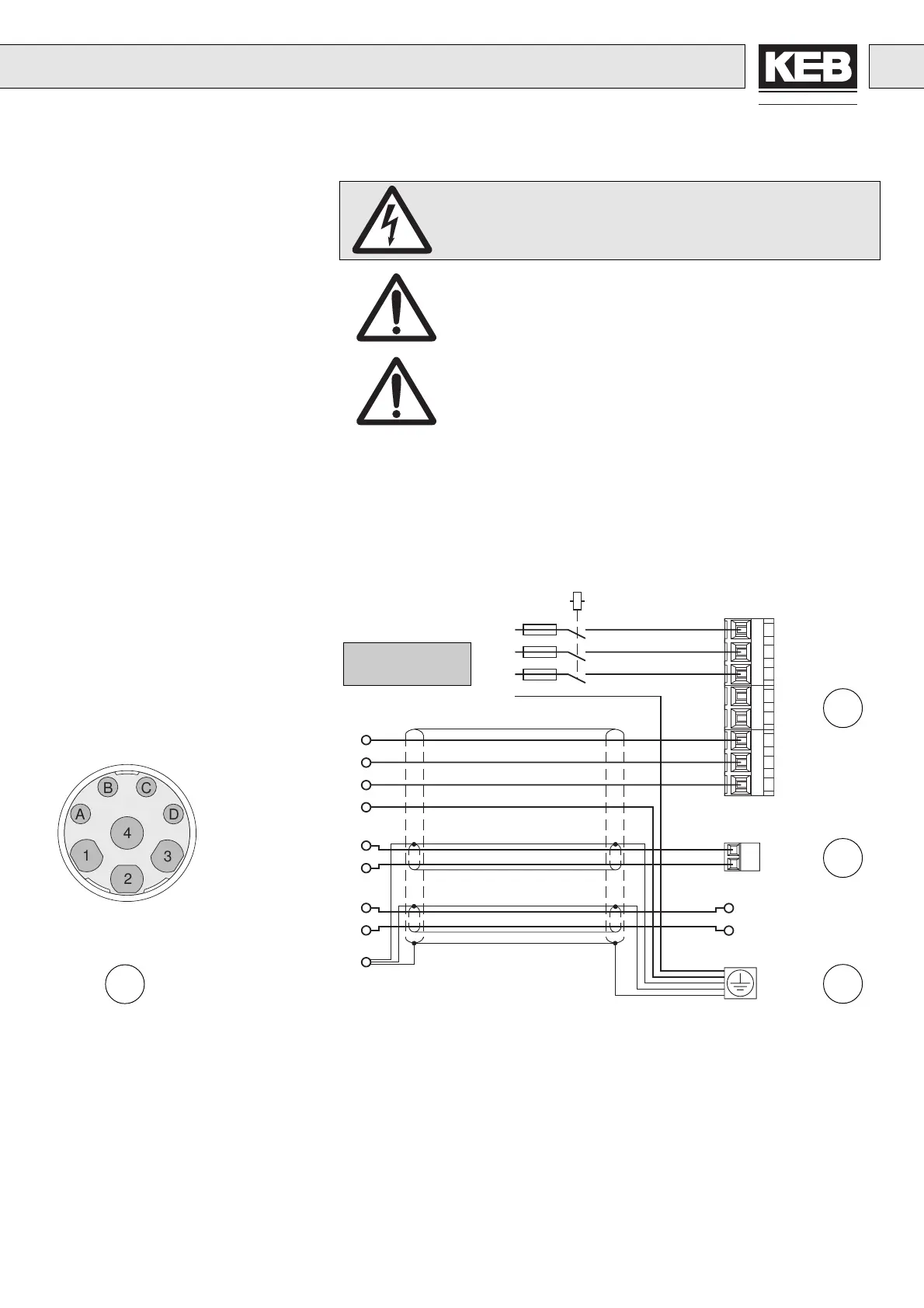
6. Connection
6.3 3-phase Connection
230 V / 400 V Class
Absolutely ensure the observance of the supply voltage
of the servo controller (3 x 230 V / 3 x 400 V) !
Remove or plug in the power connector only at switched off
unit and disconnected power supply !
Observe the correct phase sequence for the connection of
the servo motor !
}
PTC-connection
PTC-connection
Brake +
Brake –
C
D
A
B
A
B
C
D
1
2
3
4
U
V
W
PE
1
4
3
2
L1
L2
L3
PA
PB
U
V
W
OH
OH
6
7
9
8
PE Protective earth conductor
U, V, W Motor
L1, L2 Mains connection 1-phase
PA, PB Connection braking resistor
Servo motor
power connector
Motor housing/
threaded joint
Connect extensive
shield to both sides!
External brake supply
unit with own voltage
supply
L1
L2
L3
PE
Mains connection
Connector Cable
Contact No. Designation Core No.
1U1
4V2
3W3
2 PE Green-Yellow
A Brake + 5
B Brake – 6
C PTC-Contact 7
D PTC-Contact 8

 Loading...


