E 24
6. Connection
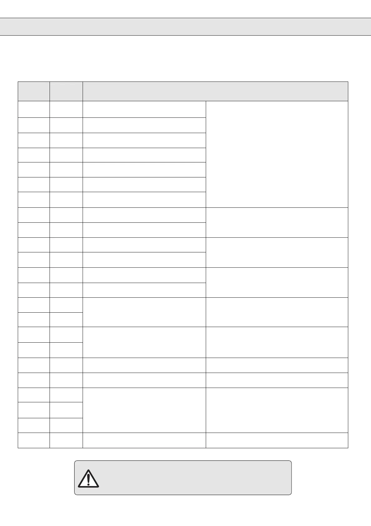
Terminal Designa- Function
tion
1 ST Control release
2 RST Reset
3F
Release of rotation direction (limit switch
*
) forward
Digital inputs: +12…33 V / Ri = 2 kΩ
4R
Release of rotation direction (limit switch
*
) reverse
PNP
5 I1 Input for jogging speed forward Potential-separated
6 I2 Input for jogging speed reverse * When the unit is defective there is no guarantee
that the software protective function will start.
7 I3 Input for external error setting
8 D1 Digital output signal 1 Programmable
PNP - transistor outputs
9 D2 Digital output signal 2 24 V / max. 20 mA
10 Uout + 24 V voltage output +24V (+/- 10%) ; max. 100 mA
11 0 V
Ground reference for +24 V and digital in/outputs
12 CRF +10 V reference voltage +10V (+/- 3%) ; max. 4 mA
13 COM Ground for analog inputs/outputs
14 REF 1 + Voltage difference input
Analog setpoint value setting - 10V… + 10V / Resolution: 12 Bit
15 REF 1 – Ri = 40 kΩ
16 REF 2 + Voltage difference input
Analog torque limitation 0…+10V / Resolution: 12 Bit
17 REF 2 –
refer to Parameter CP.9
-10V…0V = 0 Nm
/ +10V = M
max.
/ Ri = 40 kΩ
18 A1 Programmable analog output -10V…+10V / Resolution: 8 Bit Ri = 100 Ω
19 A2 Output of current speed -10V…+10V / Resolution: 8 Bit Ri = 100 Ω
20 RLA Output relay:
21 RLB RLA / RLC : normal operating condition max.250 V AC/0,2 A or 30 V DC/1 A
22 RLC RLB / RLC : POWER OFF / malfunction
23 Ext. Spg. external supply of the control + 24 V external voltage input
6.8 Control Terminal Strip X2
^^
Rotation release (terminal X2.3 / X2.4) and analog torque limitation
(terminal X2.16 / X2.17) have no function in the Drive Mode
See page E 37 "Drive Mode"

 Loading...


