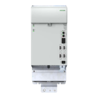
1
2
6
7
4
3
5
1.) KeDrive D3-DU controller
2.) KeDrive D3-DP supply unit BG3
3.) KeDrive D3-DC capacitance module (optional)
4.) KeDrive D3-DA BG4
5.) KeDrive D3-DA BG3
6.) KeDrive D3-DE expansion module
7.) Possible connection of KeDrive D3-DA BG1 and BG2
Figure 3.1 Butt mounting sequence
WARNING! Risk of injury due to hot surfaces on the device (heat sink)!
Carelessness may result in serious burns or damage.
• The device heats up very signicantly during operation and can reach temperatures
of up to 100°C. If touched there is a risk of burns to the skin. For this reason provide
protection against touching.
• Please maintain a sufcient distance from neighbouring assemblies, particularly above
the heat sink.
3.2 Mounting clearances
CAUTION! Damage to the device due to incorrect installation conditions!
The device may suffer irreparable damage if the conditions are not
met.
• The minimum clearances stated in the gure below apply to all devices (KeDrive D3-DU,
KeDrive D3-DP BG3 and BG4 and KeDrive D3-DA BG3 and BG4).
• The clearance above the devices is important to prevent the build-up of heat. The
clearance underneath and at the front is necessary to permit correct cable laying.
≥ 130
≥ 250
*)
D3-DP BG3
D3-DA BG3
≥ 300
*) The bending radius of the connection cables must also be taken into account:
Figure 3.2 Mounting clearances, KeDrive D3-DA BG3
16
1 Mechanical installation
Operation Manual KeDrive D3-DA BG3 and BG4
1804.200B.1-01 Date: 03/2023
Mechanical installation

 Loading...