X25A
X26A
X01A
L1
L3
L2
11
20
12
24 V
GND
X40A X40B
DC Link -
DC Link+
GND
+24 V
X48A
X48B
X48C
X48D
21
DC Link -
DC Link+
GND
+24 V
BR
X30
PE
X30
X01C
2
5
z
Netz/Line
ZK
BR
X30
BR
15
17
16
X40AX40A X40B
9
L1 L2 L3 PE
L3
L2
L1
L3.1
L2.1
L1.1
1
14
13
6
L1 N
3
X23
Motor1
3~
3
2
2 2
TEMP
BRAKE
5
4
25
10
18
7
8
L3
L2
L1
L3.1
L2.1
L1.1
WUV
Motor2
3~
3
2
WUV
TEMP
BRAKE
MOTOR 2
MOTOR 1
1818
PELV
PELV
BI
ZK
PELV
PELV
PELV
PELV
VI
PELVPELV
X20
X20
TP
PELV
PELV
ZK
PELV
BI
Netz
X20
X20
PF
EXP
PELV
PELV
PELV
BI
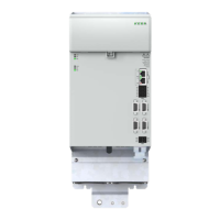
(1) Mains fuse for DC link supply (12) Axis controller KeDrive D3-DA BG3 and BG4
(2) 24 V DC power supply unit (external) (13) Switch cabinet
(3) Mains contactor (optional) (14) Field
(4) Programmable switching contact for mains contactor (15) Braking resistor with temperature monitoring (external)
(5) Mains lter (accessory) (16) Backing plate
(6) Mains choke (accessory) (17) Backing plate earthing
(7) Mains supply (DC link) (18) EtherCAT connection
(8) Supply point, switch cabinet
(9) Busbars, DC link (20) Star topology protective earth conductor via PE rail
(10) Busbars, 24 V DC (21) Capacitance module
(11) Supply unit KeDrive D3-DP (25) Cable protection 6 A gG
Figure 4.8 Electrical isolation concept with key (extract), for complete description see Figure 4.22
4.6 Connection of the supply voltages
Power is supplied to the axis controllers separately for the control section and power
section. The control section in the axis controller receives its 24 V supply from the supply
unit via the upper busbars (+24V DC and GND).
The power section in the axis controller receives its DC link supply from the supply unit
via the lower busbars (DC Link+ and DC Link-).
Step Action Comment
1.
First make sure all KeDrive D3-DA axis controllers BG3 and BG4
are arranged in a line with the KeDrive D3-DP supply unit BG3
and BG4 and they are together in a row.
See installation instructions in
Figure 3.1.
2.
Always connect rst the 24 V control supply
for the axis controllers.
If you want to use several axis controllers, all 24VDC
connections and all GND connections must be connected
together.
For this purpose use the pre-
assembled busbar elements as
per Figure 4.9. It is necessary to
unscrew the screws slightly to be
able to rotate the busbar elements.
3.
Only connect the DC link supply when you want to place the axis
controllers in operation.
If you want to use several axis controllers, all DC-Link+
connections and all DC-Link- connections must be connected
together.
For this purpose also use the pre-
assembled busbar elements as per
Figure 4.10.
4.
Once all busbar elements have been tted, the screws must be
re-tightened!
CAUTION! Risk of injury due to incorrect wiring!
Carelessness may result in injuries.
Make sure that all connections have good contact and are sufciently secure that they cannot
come loose. If connection elements are used that do not meet the requirements, KEBA does
not provide any guarantee for stable, reliable operation.
37
1 Electrical installation
Operation Manual KeDrive D3-DA BG3 and BG4
1804.200B.1-01 Date: 03/2023
Electrical installation

 Loading...