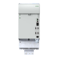
4.9 Encoder connections
All encoder connections (except HIPERFACE DSL® one-cable system) are located on
the front of the device. For terminal assignment, see chapter 4.3.1 and 4.3.2.
To connect the LSP, LSD, LSN, LST and DMS2 synchronous motors, please use the
ready-made motor and encoder cable from KEBA, see also A.8.
4.9.1 Allocation of motor/encoder cable to the drive controller
Compare the rating plates of the components. Make absolutely sure you are using the
correct components according to variant A, B or C!
additional encoders:
SinCos encoder
TTL encoder
Resolve
high- resolution encoder:
HIPERFACE®
SSI/EnDat 2.1 interface
Resolver
Variant
B
Variant
A
Motor cable
Motor cable
Encoder cable
Encoder cable
X48C (Enc.)
X48D (Enc.)
X48A (Enc.)
X48B (Enc.)
Figure 4.18 Allocation of motor/encoder (as an example a double-axis controller is shown)
NOTE:
You will nd details about the possible combinations of motor/encoder and
corresponding cables in the order catalogue "System Cables" and in the
related motor catalogues.
Document Contents ID no. Format
KeDrive D3
System
Catalogue
Overview with notes on ordering and project planning information
for: KeDrive D3 system
1404.205B.x PDF
System Cables
Order Catalogue
Overview with ordering information for motor and encoder cables
for all product ranges
0966.24B.x PDF
KeDrive DMS2
Catalogue
Main features, product overview of the servomotor range DMS2 www.keba.com PDF
LST/ LSN Order
Catalogue
Main features, product overview of the servomotor range LST and
LSN
0814.25B.x PDF
LSP Order
Catalogue
Main features, product overview of the servomotor range LSP 0814.28B.x PDF
NOTE:
Do not cut the encoder cable, for example to route the signals via terminals in
the switch cabinet. The knurled screws on the D-Sub connector housing must
be tightly locked!
47
1 Electrical installation
Operation Manual KeDrive D3-DA BG3 and BG4
1804.200B.1-01 Date: 03/2023
Electrical installation

 Loading...