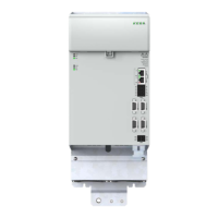
4.6.3 Overview of busbars in the group
A
Figure 4.11 Cover on the busbars
WARNING! Risk of injury due to electrical power!
Carelessness may result in serious injuries or death.
The multi-axis system is only allowed to be operated with the cover on the busbars closed! It
is also important that the side covers (A) are tted. Both provide protection against touching
bare and live parts.
4.7 Control connections
Step Action Comment
1.
Establish a connection between the EtherCAT interface
X40A on the rst axis controller and the controller
D3-DU 3xx by connecting the EtherCAT output on the
controller to connector X40A on the supply module
D3-DP 3xx. Then connect X40B on the supply module
to X40A the rst axis controller. The cables required are
included in the scope of supply of the modules.
EtherCAT interface specication
See Chapter 4.10
2.
Connect all other axis controllers to the rst axis
controller via the EtherCAT interfaces X40A and X40B
EtherCAT interface specication
See Chapter 4.10
3.
As necessary, wire the control outputs to X25A using
shielded wires.
Earth the cable shields over a large area at both ends.
See Table 4.15
4.
If you want to use the safety function STO and/or STB,
wire the safe control outputs to X26A using shielded
wires.
Earth the cable shields over a large area at both ends.
See Chapter 4.7.2
5.
Check all connections again!
39
1 Electrical installation
Operation Manual KeDrive D3-DA BG3 and BG4
1804.200B.1-01 Date: 03/2023
Electrical installation

 Loading...