≥ 130
≥ 250
*)
≥ 300
D3-DP BG4
D3-DA BG4
*) The bending radius of the connection cables must also be taken into account
Example:
Motor cable 4 x 70 mm
2
-> D = 42 mm (for D3-DA 310/x-A3xx)
(D = outside Ø of the motor cable)
Bending radius (acc. to EN 60332-1-2):
For xed laying 5 x D = approx. 210 mm
to 7 x D = approx. 292 mm
depending on the cable type
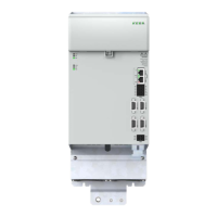
Figure 3.3 Mounting clearances, KeDrive D3-DA BG4
NOTE:
It is imperative the min. mounting clearances above and below are met for
thermal reasons. Depending on the connection cables used (mains cable/
motor cable), the mounting clearances may increase signicantly due to the
bending radii necessary.
3.3 Cooling of the devices with air cooling
Cooling air must be able to ow through the device (interior and heat sink) without
restriction. If a thermal cut-out occurs, the cooling conditions must be improved.
Note:
Due to the compact design, the
KeDrive D3 DA axis controllers
are equipped with internal fans for
optimal heat dissipation. The speed
of these fans is set as a function of
the heat sink temperature. The fan
noise may therefore vary depending
on the load.
Figure 3.4 Cooling air ows unhindered through the device
17
1 Mechanical installation
Operation Manual KeDrive D3-DA BG3 and BG4
1804.200B.1-01 Date: 03/2023
Mechanical installation

 Loading...