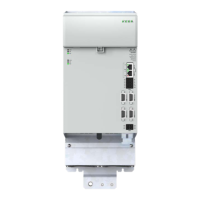
4.3.1 Single-axis controller
1
15
1
15
L/A
RUN
L/A
ERR
Axis 1
ERR
RUN
DI00
DI01
DI02
DI03
DI04
DI05
DI06
DI07
DI08
DI09
DI10
GND
X25A
X40A / IN0X40B / OUT0
EtherCAT
X48A / Axis1Enc1 X48B / Axis1Enc2
SDI00SDI02
SDI01SDI03
GNDGND
X26A
X25A
X48A
X48B
X26A
X40A
X40B
Axis 1
Figure 4.5 Layout, single-axis controller
30
1 Electrical installation
Operation Manual KeDrive D3-DA BG3 and BG4
1804.200B.1-01 Date: 03/2023
Electrical installation
Abbreviation Designation Details
X40A EtherCAT IN, input, eld bus
Can also be used as Ethernet interface
for PC with DriveManager. For
information about activating the service/
diagnostics mode, see chapter 5.1.3
X40B EtherCAT OUT, output, eld bus
X25A Digital inputs
X48A Encoder connection 1 (axis 1) Enc1 (multi-encoder interface)
X48B Additional encoder connection (axis 1) Enc2 (simple encoder interface)
X48C Does not exist
Only used for double-axis controllers.
X48D Does not exist
X26A Digital inputs, safety function
Axis 1 LED yellow
State axis 1
For details see 6.1
ERR LED red
RUN LED green
Table 4.5 Key to connection diagram for single-axis controller

 Loading...