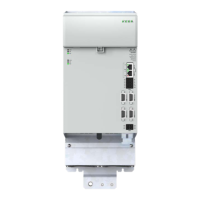
Abbreviation Designation Details
24 V DC 24 V DC busbars (control supply)
See Chapter 4.6.1
DC link DC link busbars (power supply)
See Chapter 4.6.2
Status Axis 1 Status indication axis 1
See Chapter 6.1
X40A EtherCAT® IN, input, eld bus
See Chapter 4.10
X40B EtherCAT® OUT, output, eld bus
X25A Digital inputs (programmable)
See Chapter 4.7.1
X48A Encoder interface
See Chapter 4.9.1
X48B Encoder interface
X26A Digital inputs (safety function)
See Chapter 4.7.2
S-ADR
DIL switch bank for the conguration
of the SD0 functionality
See Model description SD0
(ID no.: 1404.252B.x)
X31A Motor power connection U, V, W
See Chapter 4.8
X31A (TEMP/BRAKE)
Connection for temperature monitoring,
motor winding/motor brake
PE
Connection for protective earth
conductor/ earthing
See Chapter 4.4
Table 4.4 Key to the layout, KeDrive D3-DA BG4
29
1 Electrical installation
Operation Manual KeDrive D3-DA BG3 and BG4
1804.200B.1-01 Date: 03/2023
Electrical installation

 Loading...