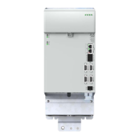
4.9.3 Connection for additional encoder (X48B and X48D)
The X48B and X48D interfaces enable evaluation of the following encoder types.
Fig.
15
1
15
L/A
RUN
L/A
ERR
ERR
RUN
DI00
DI01
DI02
DI03
DI04
DI05
DI07
DI08
DI09
DI10
GND
SDI00SDI02
SDI01SDI03
GNDGND
X25A
X48A
X48B
X26A
1
15
1
15
1
15
1
15
L/A
RUN
L/A
ERR
Axis 1
ERR
RUN
Axis 2
ERR
RUN
DI00
DI01
DI02
DI03
DI04
DI05
DI07
DI08
DI09
DI10
GND
SDI0
DI02
SDI0
DI03
GN
ND
X48C
X48D
X48C / Axis2Enc1X48D / Axis2Enc2
X40A / IN0X40B / OUT0
EtherCAT
X25A
X48A / Axis1Enc1 X48B / Axis1Enc2
X26A
X25A
X40A / IN0X40B / OUT0
EtherCAT
X48A / Axis1Enc1 X48B / Axis1Enc2
X26A
I02
I
04
I05
DI
7
DI08
DI09
DI1
ND
X25
X48
Axis2Enc1
X48A / Axis1Enc1
DI
DI
2
DI
DI
ND
ND
26
DI
DI
1
ND
I02
I
04
I05
I
7
I08
I09
I1
GND
25
X48A / Axis1Enc1
DI
2
DI
ND
26
Function
SinCos encoder with zero pulse e.g. Heidenhain ERN1381, ROD486
TTL encoder
Resolver
1 pole pair to 5 pole pairs. From revision state "F". Only one resolver per axis!
Figure 4.20 Suitable encoder types on X48B and X48D
NOTE:
The usage of encoders not included in the range supplied by KEBA requires
special approval from KEBA.
The maximum signal input frequency is 500 kHz.
Encoders with a voltage supply of 5V must use the supply from pin 3
(typ.5.25V, max. 5.4V).
NOTE:
The encoder supply on X48B and X48D is short-circuit proof during both
5V and 10V operation. The controller remains in operation enabling the
generation of a corresponding error message while evaluating the encoder
signals.
4.9.4 Connection of analog sensors (X48B)
Using the D3-XA 230/A analog adapter, two analog sensors (e.g. pressure sensor, load
cell) can be connected directly to the X48B encoder connection. This makes it possible
to record forces or pressures occurring in the system. These measured variables can be
used further in the system with the aid of the hydraulic control or the process controller.
In order to keep the reaction time as short as possible, the control takes place directly in
the axis controller.
NOTE:
Further information on the use and connection of the analog adapter can be
found in the instruction leaet Id no.: 1804.013B.x.
4.10 Specication
The EtherCAT® eld bus interface X40A is typically used for the connection of the
controller KeDrive D3-DU or another EtherCAT®-compliant controller with EtherCAT
master.
It can also be used as a service and diagnostics interface. However, it is then only
suitable for the connection of a PC for commissioning, service and diagnostics using the
software KeStudio DriveManager (if you have any questions on this topic, please contact
us).
NOTE:
EtherCAT® is specied in IEC61158 and IEC61784. You will nd general
information about EtherCAT® at www.ethercat.org
EtherCAT® is a registered trade mark and patented technology licensed by
Beckhoff Automation GmbH, Germany.
49
1 Electrical installation
Operation Manual KeDrive D3-DA BG3 and BG4
1804.200B.1-01 Date: 03/2023
Electrical installation

 Loading...