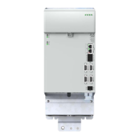
Technical specication:
y Transfer rate 10/100 Mbits/s BASE-T
y Transfer prole IEEE802.3-compliant
y Shielding of the connector over the entire connector length
Des. Term. Specication Figure
IN0
Input, EtherCAT®
X40A
Connection via RJ45
connector
L/A
RUN
L/A
ERR
Axis 2
ERR
RUN
Axis 3
ERR
RUN
DI00
DI01
DI02
DI03
DI06
DI07
DI08
DI09
DI10
GND
SDI00 SDI02
GNDGND
SDI01SDI03
X26A
X40A
X40B
2
3
Statusanzeige:
1)
1)
Siehe Kapitel
5 Diagnose
X48C / Axis2Enc1X48D / Axis2Enc2
X40A / IN0X40B / OUT0
EtherCAT
X25A
X48A / Axis1Enc1 X48B / Axis1Enc2
X26A
X25A
Axis 2
Axis 3
RR
00
1
02
I03
I07
08
I09
is2Enc2
X25A
X48A / Axis1Enc1
2
OUT0
Output, EtherCAT®
X40B
LEDs Ethernet ports
L/A Green Port0 Link / Activity
RUN Green Device / EtherCAT RUN
L/A Green Port1 Link / Activity
ERR Red Device / EtherCAT ERROR
Table 4.19 EtherCAT ports
Connect the modules using the cable supplied. The length of the cable always permits
connection to the neighbouring module on the left. If longer cables are required (e.g.
for EtherCat master located remotely from the axis block), use the following cable or an
equivalent cable:
y Cat. 5e patch cable, S/STP 4x2x0.14 mm
2
, twisted pair and shielded data
cable with characteristic impedance R
w
= 100 Ω ±15%
NOTE:
For cable lengths ≥ 20 m, special installation cables with larger cross-sections
are to be used.
Connection example
Figure 4.21 EtherCAT® connection (example)
50
1 Electrical installation
Operation Manual KeDrive D3-DA BG3 and BG4
1804.200B.1-01 Date: 03/2023
Electrical installation

 Loading...