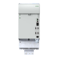
Connection example, supply unit / axis controller
X25A
X26A
X01A
X23A
L1 L3L2
24 V
GND
BR
BR
X01C
n.c.
X40A X40B
DC Link -
DC Link+
GND
+24 V
X30A
X20A
TP
X48A
X48B
X48C
X48D
X40B X40A
L1 L2 L3 PE
L3
L2
L1
L3.1
L2.1
L1.1
V AC/
V DC
Motor1
3~
3
2
2
BRAKE
TEMP
L3
L2
L1
L3.1
L2.1
L1.1
WUV
Motor2
3~
3
2
2
BRAKE
TEMP
WUV
MOTOR 2
MOTOR 1
5
z
Netz /Line
11
16
10
9
21 21
22
22
23
23
19
12
18
1
14
13
5
3
6
15
2
Figure 4.22 Connection example (schematic depiction)
Key to connection example
Designation
(1) (2) (3) (4)
(5) (6) (7) (8)
See Operation Manual KeDrive D3-DP
Supply Unit
(9) DC link busbars
(10) 24 V DC control supply busbars
(11) KeDrive D3-DP supply unit BG3 and BG4
(12) KeDrive D3-DA axis controllers BG3 and BG4
(13) Switch cabinet
(14) Field
(15)
See Operation Manual KeDrive D3-DP
Supply Unit
(16) Backing plate
(17)
See Operation Manual KeDrive D3-DP
Supply Unit
(18) PE - protective earth conductor connection, motor(s)
(19)
Star topology protective earth conductor connection for the
devices on PE rail
(21) EtherCAT® ports
(22) Motor holding brake connection
(23) Motor temperature monitoring connection
Table 4.20 Key to connection example
NOTE:
A maximum of 8 communication bus users can
be connected to and operated on a supply unit.
A communication group is allowed to consist of a
maximum of 9 bus users.
51
1 Electrical installation
Operation Manual KeDrive D3-DA BG3 and BG4
1804.200B.1-01 Date: 03/2023
Electrical installation

 Loading...