59
1.5 Voltage/current regulator
1.5.1 Main wiring check
Remove 4p plug of the voltage/current regulator.
Check conductivity between main wiring terminals.
Item (wire color) Judgment
Between
Battery(red) and
GND of the body
With battery voltage
Between GND
wire (black) and
GND of the body
With lead
Between charging
coil (white) and
the GND of the
body
Resistance in the coil
of the magnetor.
Between lighting
cable (green/red)
and the GND of
the body (resistor
plug; automatic
side starter plug;
remove the
lighting switch
and check it at the
“OFF” position)
Resistance in the coil
of the magnetor.
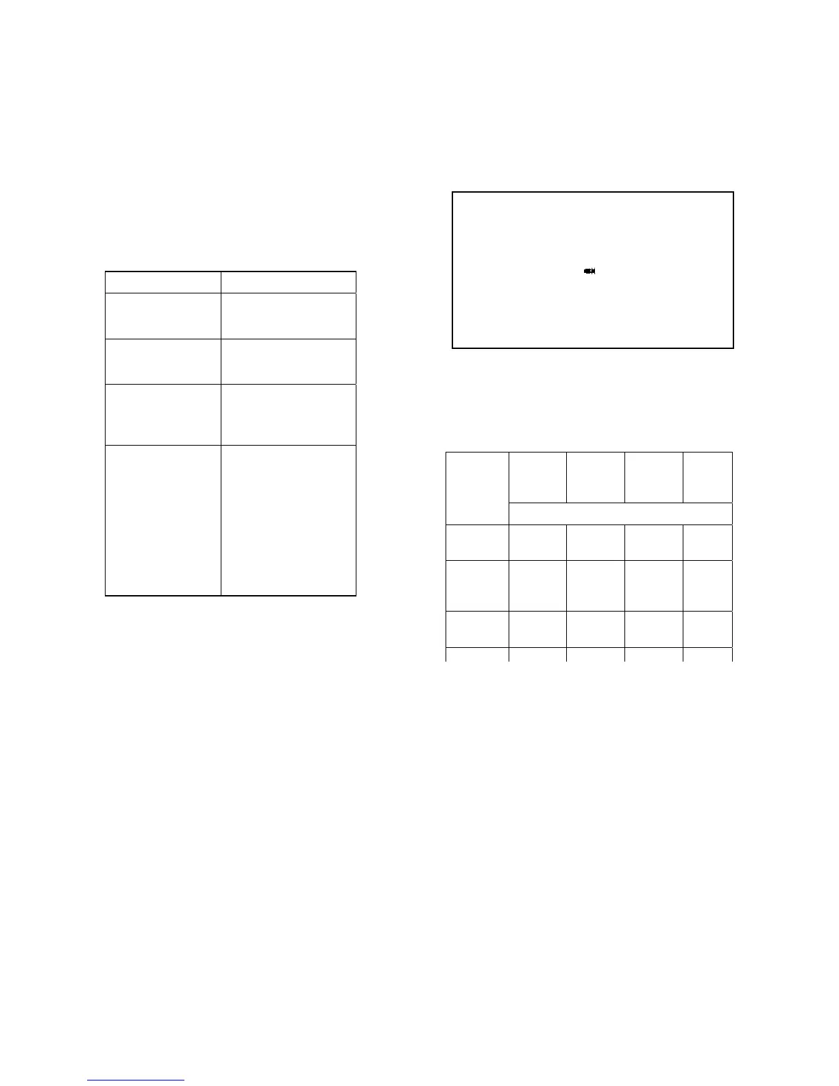
1.5.2 Voltage-current regulator check
When the main cable is inspected to be normal, check whether the plug of the voltage/current regulator is in good
contact. Measure impedance between terminals of the voltage/current regulator.
* Note
• Do not touch any metal part of the test rod of the multimeter with your finger for check.
• Check with multimeter. Different multimeters show different impedance and different results.
Replace the voltage-current regulator when the impedance between terminals is abnormal.
1.6 Magnetor charging coil
* Note
Check the magnetor charging coil on the engine.
White
(A)
Green/r
ed
(L)
Red
(B)
Black
(E)
Multimeter
Positive
Negative
Unit:MΩ
White(
A)
0 6.5 19~21
Green/
red(L
)
1~10 24~25 19~23
Red(B
)
10~50 0 19~21
Black(
5~15 0 0
 Loading...