Connections for firmware revision A13 and lower
Figure 2-7 shows synthesizer connections for revision A13 and lower.
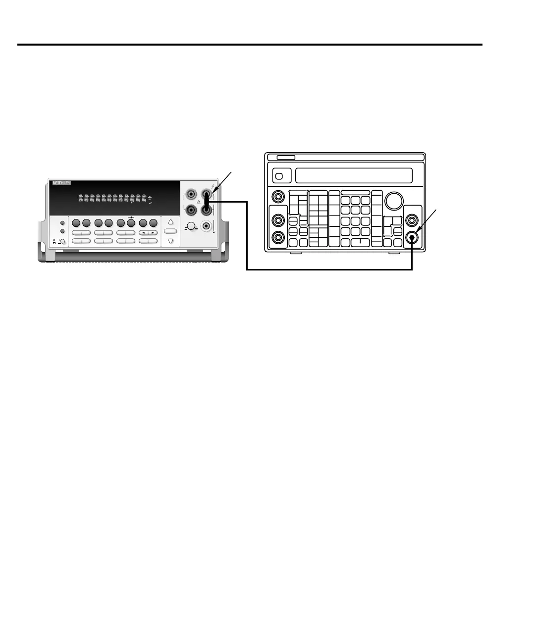
Figure 2-7
Synthesizer connections for manufacturing calibration (firmware revision A13 and lower)
Unlocking manufacturing calibration
To unlock manufacturing calibration, press and hold in the OPEN key while turning on the
power.
Calibration for firmware revision A14 and higher
Front panel manufacturing calibration (firmware A14 and higher)
1. Connect the low-thermal short to the rear panel input jacks, and select the rear inputs
with the INPUTS switch. Allow three minutes for thermal equilibrium.
2. Press in and hold the OPEN key while turning on the power.
3. Press SHIFT then CAL, select RUN, then enter the appropriate calibration code (default:
002010).
4. Select ALL at the CAL:RUN prompt.
5. Press ENTER.
6. Perform the entire front panel comprehensive calibration procedure discussed earlier in
this section. (See “Comprehensive calibration” earlier in this section.)
Model 2010
2010 MULTIMETER
RANGE
!
F
500V
PEAK
FRONT/REAR
3A 250V
AMPS
HI
LO
INPUTS
350V
PEAK
1000V
PEAK
SHIFT
LOCAL
POWER
RANGE
R
SHIFT
CH1REM
TALK
LSTN
SRQ
STAT
REL FILT
4W
BUFFER
MATH
REAR
SCAN
TIMER
STEP CH2 CH3 CH4 CH5 CH6 CH7 CH8 CH9 CH10
HOLD TRIG FAST MED SLOW AUTO ERR
INPUT
SENSE
Ω 4 WIRE
AUTO
EXIT ENTER
DIGITS RATE
RELFILTER
TRIG
EX TRIG
STORE
RECALL
OPEN CLOSE
DCV
DCI
MX+B
%
dBm
ACV
ACI
Ω2 Ω4
FREQ
TEMP
dB
CONT
PERIOD SENSOR
LIMITS ON/OFFDELAY
HOLD
SAVE SETUP
CONFIG HALT
TYPE
RS232
GPIB
RATIO
STEP SCAN
DRYCKT O COMP
CAL TEST
BNC-to-Dual
Banana Plug
Adapter
50Ω BNC Coaxial Cable
Model 3930A or 3940 Synthesizer
Main
Function
Output
2-22 Calibration