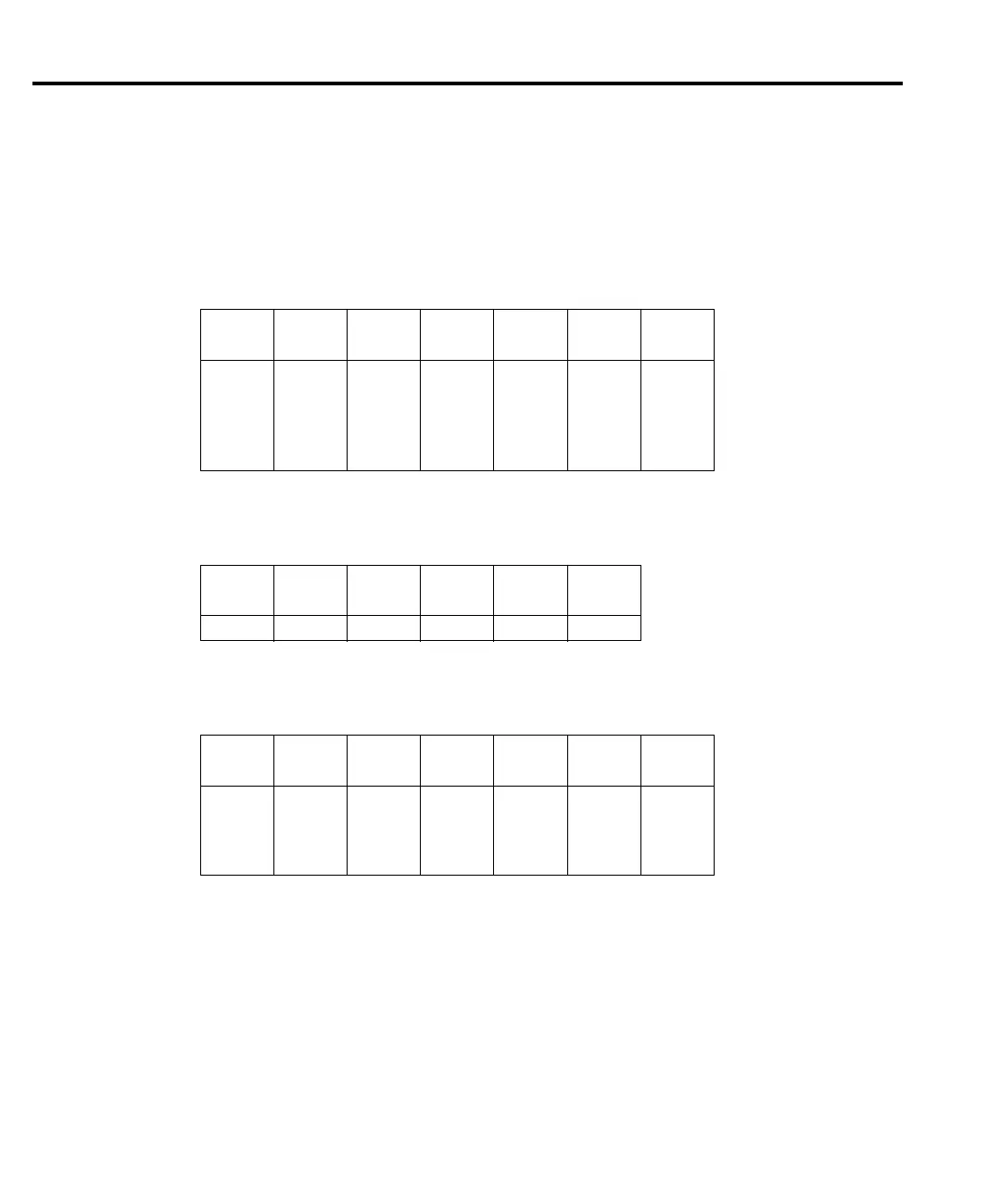
Table 4-12 through Table 4-16 can be used to trace the analog signal through the A/D multi-
plexer (U163) to the final amplifier stage. These tables show the MUX lines (S3, S4, S6, S7) that
are selected for measurement during the SIGNAL phase of the multiplexing cycle. Also included
are switching states of analog switches (U176) that set up the gain for the final amplifier stage
(U177).
Table 4-12
DCV signal multiplexing and gain
Range
Signal
(U163)
U176
pin 1
U176
pin 8
U176
pin 9
Gain
(U177)
U129
pin 16
100mV
1V
10V
100V
1000V
S4
S4
S4
S4
S4
OFF
OFF
OFF
OFF
OFF
OFF
OFF
ON
OFF
ON
OFF
ON
OFF
ON
OFF
X100
X10
X1
X10
X1
ON
OFF
OFF
OFF
OFF
Table 4-13
ACV and ACA signal multiplexing and gain
Range
U176
pin 1
U176
pin 8
U176
pin 9
Gain
(U177)
U129
pin 1
All ON ON OFF X1 OFF
Table 4-14
DCA signal multiplexing and gain
Range
Signal
(U163)
U176
pin 1
U176
pin 8
U176
pin 9
Gain
(U177)
U176
pin 16
10mA
100mA
1A
3A
S6
S6
S6
S6
OFF
OFF
OFF
OFF
OFF
OFF
OFF
OFF
OFF
OFF
OFF
ON
X100
X100
X100
X10
ON
ON
ON
OFF
4-16 Troubleshooting