6. Source the nominal full-scale resistance values for the 10Ω-10MΩ ranges summarized
in Table 1-6, and verify that the readings are within calculated limits.
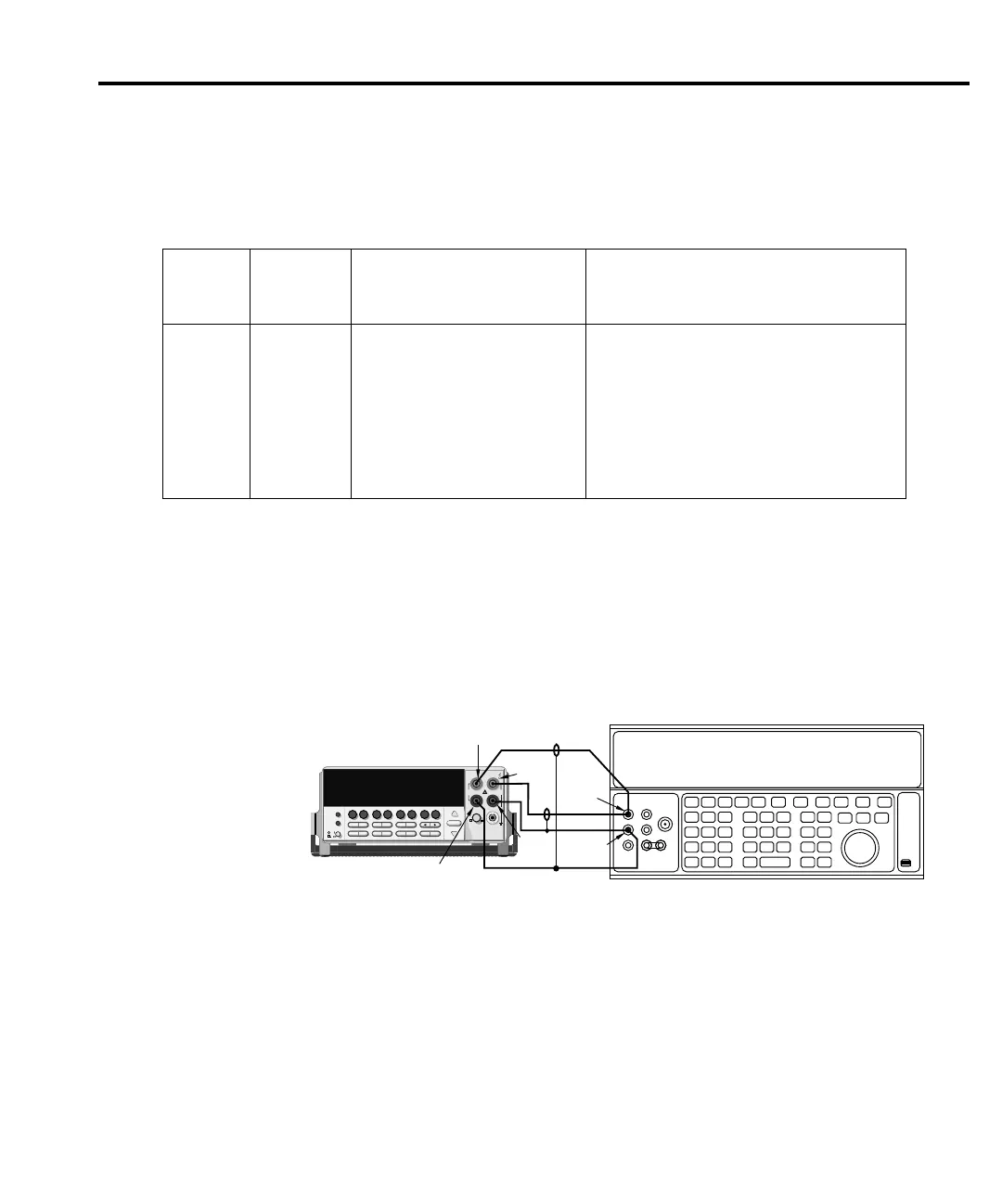
7. Connect the Model 2010 INPUT and SENSE jacks to the calibrator as shown in
Figure 1-6.
8. Disable external sense on the calibrator.
9. Set the Model 2010 for the 100MΩ range.
10. Source a nominal 100MΩ resistance value, and verify that the reading is within
calculated limits for the 100MΩ range.
Table 1-6
Limits for resistance verification
Ω range
Nominal
applied
resistance
Nominal reading limits
(1 year, 18°C–28°C) Recalculated limits*
10Ω
100Ω
1kΩ
10kΩ
100kΩ
1MΩ
10MΩ
100MΩ
10Ω
100Ω
1kΩ
10kΩ
100kΩ
1MΩ
10MΩ
100MΩ
9.999310 to 10.000690Ω
99.99390 to 100.00610Ω
0.9999480 to 1.0000520kΩ
9.999480 to 10.000520kΩ
99.99260 to 100.00740kΩ
0.9999260 to 1.0000740MΩ
9.995960 to 10.004040MΩ
99.84960 to 100.15040MΩ
______________ to_____________ Ω
______________ to_____________ Ω
______________ to_____________ kΩ
______________ to_____________ kΩ
______________ to_____________ kΩ
______________ to_____________ MΩ
______________ to_____________ MΩ
______________ to_____________ MΩ
* See verification limits.
2000 MULTIMETER
!
R
Model 2010
5700A Calibrator (Output 2-wire Resistance)
Output
HI
Input
LO
Output
LO
Note : Use shielded cables to minimize noise.
Disable calibrator external sense mode.
Sense HI
Sense LO
Input
HI
gure
-
onnections for
resistance verification
(100M
Ω
range)
Performance Verification 1-11