Voltage and Temperature Measurements 2-15
Also note that channel voltage differential reduces the maximum measurement capability of
Channel 2. Normally, Channel 2 can measure up to 12V. However, a 2V differential reduces the
maximum measurement capability of Channel 2 to 10V. In Figure 2-5A, a >10V input to
Channel 2 will cause an overflow condition.
NOTE Channel 2 HI or LO cannot be more than 12V peak from Channel 1 LO.
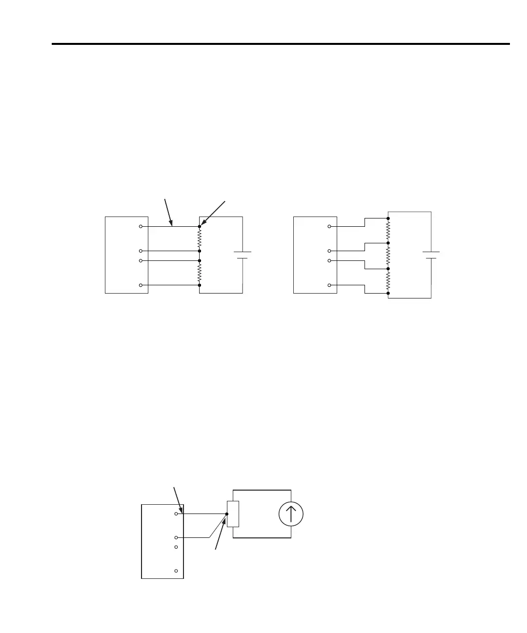
Figure 2-5
Connections - dual channel voltage
Temperature only connections
Channel 1 of the Model 2182 can be used to make temperature measurements. Figure 2-6
shows connections using the internal reference junction. Keep in mind that the thermocouple
wires must be soldered directly to a LEMO connector as previously explained.
Figure 2-6
Connections - temperature (internal reference)
Test Circuit
DUT
HI
HI
LO
LO
black
green
red
white
DCV1
CH 1
CH 2
2182
2107
Input Cable
Cable-to-copper
wire connection
(one of four)
DCV2
DUT
A. Typical Measurement Configuration
DUT
#1
HI
HI
LO
LO
black
green
red
white
DCV1
CH 1
CH 2
(10V range)
2182
DCV2
DUT
#2
B. Voltage Differential Between Channels
10V
R2V
7V
1V
Note: Channel 2 HI or LO must not exceed 12V from Channel 1 LO.
Test Circuit
DUT
HI
HI
LO
LO
black
red
TEMP1CH 1
CH 2
2182
Thermocouple wire
soldered directly to
LEMO connector
(one of two)
Thermocouple

 Loading...


