Remote Operation 11-7
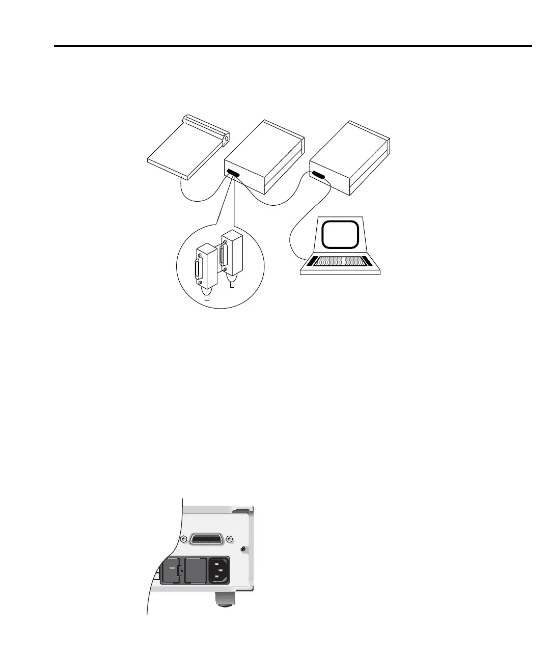
Figure 11-2
IEEE-488 connections
To avoid possible mechanical damage, stack no more than three connectors on any one unit.
NOTE To minimize interference caused by electromagnetic radiation, use only shielded
IEEE-488 cables. Available shielded cables from Keithley are Models 7007-1 and
7007-2.
To connect the Model 2182 to the IEEE-488 bus, follow these steps:
1. Line up the cable connector with the connector located on the rear panel. The connector
is designed so that it will fit only one way. Figure 11-3 shows the location of the
IEEE-488 connector.
Figure 11-3
IEEE-488 connector location
Instrument
Controller
InstrumentInstrument
WARNING:NO INTERNAL OPERATOR SERVICABLE PARTS,SERVICE BY QUALIFIED PERSONNEL ONLY.
WARNING:NO INTERNAL OPERATOR SERVICABLE PARTS,SERVICE BY QUALIFIED PERSONNEL ONLY.
CAUTION:FOR CONTINUED PROTECTION AGAINST FIRE HAZARD,REPLACE FUSE WITH SAME TYPE AND RATING.
CAUTION:FOR CONTINUED PROTECTION AGAINST FIRE HAZARD,REPLACE FUSE WITH SAME TYPE AND RATING.
RS232
120
1
35
2
46
VMC
EXT TRIG
FUSE LINE
250mAT
(SB)
100 VAC
120 VAC
125mAT
(SB)
220 VAC
240 VAC
WITH ANALOG OUTPUT
GAIN SET TO 1:
±FULL SCALE READINGS
PRODUCE ±1V OUTPUT
TRIGGER
LINK
!
LINE RATING
50, 60
400HZ
17 VA MAX
IEEE-488
(CHANGE IEEE ADDRESS
FROM FRONT PANEL)
!
!
ANALOG OUTPUT
1KΩ OUTPUT
RESISTANCE
MADE IN
U.S.A.
 Loading...


