2-14 Voltage and Temperature Measurements
To make these customized connections, you can modify the supplied input cable, or you can
use the LEMO connector that is included with the optional Model 2182-KIT.
CAUTION Silver solder has a high temperature melting point. Take care not to damage
the LEMO connector by applying excessive heat.
Voltage only connections
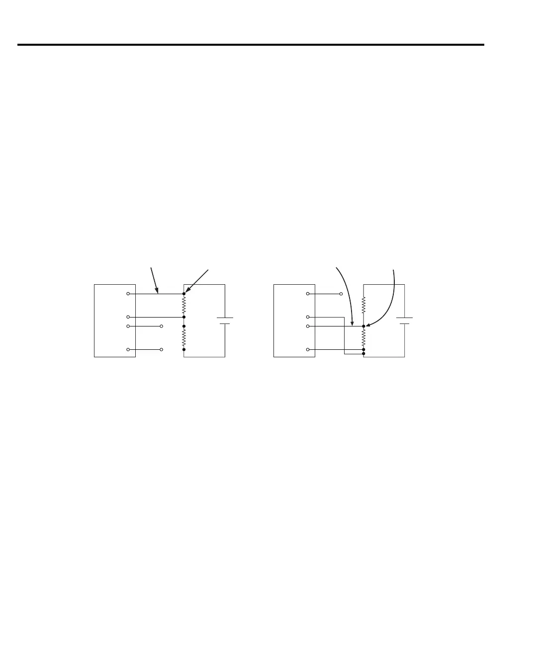
Single Channel Measurement Connections — Figure 2-4 shows typical connections to
measure a DUT using a single channel. When using Channel 2, its inputs must be referenced to
Channel 1 LO as shown in FFigure 2-4B.
Figure 2-4
Connections - single channel voltage
Dual Channel Measurement Connections — The dual channel feature of the Model 2182
allows you to make comparison measurements within a test circuit. Figure 2-5A shows typical
connections to make comparison measurements of two devices in a test circuit. For this
measurement configuration, there is no voltage differential between the two measurement
channels. Channel 2 HI is connected directly to Channel 1 LO.
Figure 2-5B shows a measurement configuration that has a voltage differential between two
channels. The differential is the 2V drop across R. Channel 1 measures voltage across DUT #1
and Channel 2 measures voltage across DUT #2. Internally, the A/D converter references
Channel 2 measurements to Channel 1 LO. For example, if 1V is being input to Channel 2 and
there is a 2V differential between the two channels, 3V will be applied to the A/D converter.
Therefore, if Channel 2 is on the 1V range, the 3V applied to the A/D converter will cause it to
overflow. The 1V measurement on Channel 2 can only be performed on the 10V range.
Test Circuit
DUT
HI
HI
LO
LO
black
green
red
white
DCV1
CH 1
CH 2
2182
2107
Input Cable
Cable-to-copper
wire connection
(one of two)
R
LEAD
A. Channel 1 Measurements
Test Circuit
DUT
HI
HI
LO
LO
black
green
red
CH 1
CH 2
2182
2107
Input Cable
Cable-to-copper
wire connection
(one of three)
R
LEAD
B. Channel 2 Measurements
white
DCV2

 Loading...


